Thursday, April 25, 2024

Transformation Relationship of IMU Coordinate Axes


Application of High Accuracy North-Seeking MEMS IMU

1. Transformation relationship of IMU coordinate axes

1.1IMU coordinate system

An IMU (Inertial Measurement Unit) is a sensor device that integrates an accelerometer, gyroscope, and magnetometer and is used to measure and calculate the acceleration, angular velocity, and direction of an object.

The IMU coordinate system is a reference coordinate system determined by the IMU sensor and consists of three coordinate axes: x-axis, y-axis, and z-axis.

The IMU coordinate system is usually referenced to three mutually perpendicular axes, and the specific directions vary depending on the device.

2. Definition of coordinate axes

x-axis: parallel to the IMU device and pointing to the front of the device.

y-axis: parallel to the IMU device, pointing to the right side of the device.

z-axis: parallel to the IMU device, pointing toward the top of the device.

3. Coordinate transformation relationship of IMU

There is a certain transformation relationship between the IMU coordinate system and the inertial space coordinate system.

This transformation relationship can be expressed by a rotation matrix, usually denoted as R, which is the rotation relationship between the inertial space coordinate system and the IMU coordinate system.

Assuming that the coordinates of the inertial space coordinate system are P and the coordinates of the IMU coordinate system are P’, the transformation relationship between the two can be expressed as: P’ = R * P.

This transformation relationship is determined by the placement angle of the sensor. Through calibration and precise measurement, an accurate rotation matrix can be obtained.

In addition, since IMU devices usually have errors, calibration and filtering operations are required to improve measurement accuracy and reduce errors.

4.Application

4.1Pose estimation

By monitoring the object's acceleration and angular velocity through the IMU sensor, the object's attitude can be estimated using the transformation relationship of the coordinate axes.

Posture represents the direction and rotation state of an object in three-dimensional space, and is widely used in fields such as robots, drones, and virtual reality.

4.2Sports tracking

The IMU sensor is used to measure the acceleration and angular velocity of an object, and the movement trajectory of the object can be tracked based on the transformation relationship of the coordinate axes.

Motion tracking technology is often used in sports training, posture analysis, sports simulation and other fields, and is crucial for accurately measuring and analyzing the motion status of objects.

4.3Posture control

By measuring the acceleration and angular velocity of the object through the IMU sensor, and combining the transformation relationship of the coordinate axes, the posture control of the object can be achieved.

Posture control is widely used in robots, smart wearable devices, game controllers and other fields to achieve precise motion control and interactive experience.
The transformation relationship of the IMU coordinate axis describes the rotation relationship between the inertial space coordinate system and the IMU coordinate system.

Through precise calibration and measurement, an accurate rotation matrix can be obtained, which is used to transform the coordinate system and implement application scenarios such as attitude estimation, motion tracking, and posture control.

Conclusion

The transformation relationship of the IMU coordinate axes is described by the rotation matrix.
Through calibration and precise measurement, an accurate rotation matrix can be obtained, thereby realizing the conversion relationship between the inertial space coordinate system and the IMU coordinate system. The MEMS IMU independently developed by ERICCO has higher accuracy. For example, ER-MIMU-01 is a navigation level with built-in Gyro bias instability: 0.02 deg/hr, and ER-MIMU-08 is a tactical level with built-in Bias instability ≤1°/h.
In practical applications, understanding the transformation relationship of IMU coordinate axes is of great significance for tasks such as attitude estimation and motion tracking. Welcome to consult.
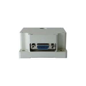
Measurement of Moving Airfoil Deflection based on Wireless Tilt Sensor

 Based on the underlying measurement principle of the tilt sensor, considering the sensor system error, operation and installation error, and referring to the existing spatial Angle error analysis model, we improve the spatial Angle biaxis measurement error model suitable for the situation of moving airfoil deflection around the horizontal axis, and improve the calibration method according to the working condition. By using wireless transmission as a communication method, a complete set of moving wing deflection test system is built, which can display the Angle information of the moving wing in real time by visual means such as data, curves and three-dimensional models. The deflection Angle measurement accuracy is less than 0.05°, and the acquisition frequency is higher than 10 Hz, which can meet the actual measurement requirements.

Modern aircraft manufacturing mainly adopts modular assembly technology, the whole aircraft components in the assembly line to complete modular manufacturing and equipment installation test, and finally complete the docking of large parts on the final assembly pulsating production line to form the whole machine. For large aircraft, there are many types and quantities of movable airfoil, high profile accuracy requirements, many control and coordination links involved, large manufacturing and debugging workload, and complex installation and debugging processes.

The detection of deflection Angle is an important part of modular wing assembly test. There are many types and complex structure of the rudder surface of a certain key model, and the tilt sensor equipment installation of the traditional method of wing deflection Angle detection is cumbersome, the types of mechanical fixtures required are large, and the operation of workers is time-consuming and laborious. With the growing demand for various types of high-performance aircraft, the manufacturing tasks of aircraft manufacturers are increasing, and the production line needs an accurate, fast and real-time movable wing automatic inspection operating system that can reflect the production process in real time to improve the production line efficiency and ultimately increase the aircraft output.
At present, the commonly used methods to detect the deflection Angle of the active airfoil space include inertial measurement, laser tracker detection, visual detection, coordinate detection, multi-theodolite detection, linear displacement or angular displacement sensor indirect detection, mechanical protractor, etc. The methods are various, but all have certain shortcomings. Therefore, many studies have combined the above methods to improve the accuracy and applicability of measurement. The inertial measurement method based on tilt sensor is relatively portable, the measurement accuracy and efficiency can meet the actual demand, so we finally choose this method to test the deflection of moving airfoil.

System design and implementation

(1) A biaxial measurement error model is proposed for the scenario of the active airfoil deflecting around the horizontal axis. Considering the actual working conditions of the active airfoil deflecting, a new error variable is introduced to improve the calibration algorithm, so that the tilt sensor calibration algorithm can adapt to the special working conditions of the unparallel mounting surface. The calibrated sensor Angle output accuracy is improved, and the error is within the allowable range, which can meet the high precision testing requirements of the wing moving surface Angle.
(2) Complete the design and implementation of a large aircraft wing active wing deflection test system based on wireless communication protocol, and the field verification that it can achieve the mission objectives. Compared with the previous system, the hardware installation of the system does not need to connect wired communication cables, and the operation is simple. The calibration work can be automatically completed through software control, and the accuracy and real-time performance of data transmission under the wireless network can also be guaranteed, which can significantly improve the work efficiency of field active wing deflection test.
(3) Only installation errors were considered in the analysis of the measurement model of spatial Angle. In fact, there is coupling between all kinds of errors. In the subsequent research, we can try to identify all kinds of errors of the system as a whole to improve the measurement accuracy of the calibration model.

Summary

Ericco's two very popular wireless tilt sensors, ER-TS-12200-Modbus, accuracy can reach 0.001°, resolution 0.0005°, ER-TS-32600-Modbus accuracy moderate 0.01°, resolution 0.002°, you can choose according to your own needs, If you are interested in our wireless tilt sensors, please feel free to contact us.

Tuesday, April 23, 2024

Research on Operating Error of Fiber Optic Gyro across Stripes

 After nearly 20 years of development, the domestic interferometric fiber optic gyro is becoming mature, and has completely replaced the mechanical gyroscope in many fields, and has become a key component in modern navigation instruments. With the development of the modulation mode of fiber optic gyro from analog triangle wave to digital square wave, the precision of fiber optic gyroscope is gradually improved.

1 Fiber optic gyro modulation mode

The modulation modes of fiber optic gyro mainly include two state modulation, four state modulation and random modulation

1.1 Two-state modulation scheme

The two-state modulation scheme adopts the modulated mode of +π-θ, square wave of 0 plus step wave (θ is the biased phase), and the typical two-state modulation waveform is shown in Figure 1. The high and low level of the phase square wave and the interference of the previous state form two interference phases of +π-θ and -π+θ, respectively. Rate step waves are generated to offset the phase shift caused by the input angular rate, and the height of each step should be equal to the phase shift caused by the input angular rate, so that the operating point can be stabilized at +π-θ and -π+θ. When the step wave accumulates out of the range 0 ~ 2π, only 2π reset of the rate step wave is needed to realize the modulation of the fiber optic gyro.
Since the responses of +π-θ and -π+θ to the diagonal acceleration of the two operating points are opposite, the angular acceleration can be demodulated by the light intensity difference between the two points.

1.2 Four-state modulation scheme

Because the two operating points of the two-state modulation are symmetric about the Y-axis, the demodulation half-wave voltage gain cannot be stabilized. To solve this problem, A set of fixed +π+θ, 0 square waves can be added on the basis of two-state modulation to generate stable +π+θ, +π-θ, -π+θ and -π-θ operating points (denoted as A, B, C, D). This modulation scheme is called four-state modulation.

1.3 Random modulation scheme

In order to solve the problem of dead zone and zero deviation caused by crosstalk, a random modulation scheme is adopted in this paper. The errors introduced by electron crosstalk can be cancelled out by using the randomly generated four-state modulated signal instead of the modulated square wave of the original fixed sequence, so the dead zone and zero deviation problems can be effectively suppressed. Since the phase waveform of random modulation ranges from -2π to +2π and the rate step wave ranges from 0 to 2π, the final shape of the modulated wave ranges from -2π to 4π. At a half-wave voltage of 4V, a modulation amplitude of 6π requires a voltage range of 6V. Therefore, in this paper, the step wave and the modulation phase are superimposed and then 2π reset. The reset mode is fundamentally different from the step wave reset mode and is called "group reset mode".

3 Cross-stripe work effects

3.1 Nonlinear deterioration at high speed

Since the modulation mode reconfiguration of two-state modulation and four-state modulation occurs only when the rate step wave is out of the range 0 ~ 2π, it is highly correlated with the step wave, but not with the modulation phase. Therefore, the probabilities of the four states A, B, C, and D working across the fringes are exactly equal.
According to the angular acceleration demodulation formula (1) and (2), it can be seen that the angular rate errors caused by the cross-fringes of A and B are of opposite polarity (the same is true for C and D). Therefore, in demodulation of angular acceleration, most of the errors caused by cross-fringe operation are statistically offset (A and B offset, C and D offset). The nonlinear errors of two-state modulation and four-state modulation with frequent cross-fringes at high speed can be suppressed to a lower degree. In the random modulation scheme using the "combined reset mode", the modulation signal is A, B, C, D four states of the modulation phase and angular rate step wave superimposed together, and then determine whether to reset. Therefore, the cross-fringe probabilities of the four modulated states are closely related to their own phases, resulting in huge differences in the cross-fringe probabilities of the four states A, B, C and D, and the cross-fringe errors are difficult to offset each other. Since the relationship between the probability and the input Angle rate is nonlinear, the error cannot be synthesized linearly by the input Angle rate, so a 500×10-6 nonlinear error is generated.

3.2 Zero bias stability decreases

In a single demodulation cycle, using the step wave 2π reset or the combination reset formula, the light intensity error of the cross-stripe work will be mistakenly demodulated. The error appears in the form of noise in the Angle addition rate demodulation and half-wave voltage gain demodulation of the optical fiber Dorrata, which worsens the zero-bias stability.

3.3 Total temperature zero drift increases

The half-wave voltage gain closed-loop cannot keep the light intensity of each operating point consistent in the cross-fringe operation because of the cross-fringe error.
If only A, B, C, D4 operating points in the zero-order fringe are considered to demodulated the half-wave voltage gain, then there is an error between the obtained half-wave voltage gain and the physical parameters of the Y-waveguide, and the error changes with the change of half-wave voltage gain, resulting in a whole-temperature zero-bias drift.

4 cross-stripe working error solution

Using narrow-spectrum light source can greatly improve the interference spectrum and reduce the cross-fringe error. But the narrow spectrum light source will reduce the coherence coefficient, resulting in the host interference, resulting in the decline of the precision of fiber optic gyro. Because of this, it is not feasible to use narrow spectrum light source to solve the cross-fringe error.
Another solution is to set the bias phase θ to 0.5π, which has the smallest difference in cross-fringe light intensity and can reduce the cross-fringe error. However, the bias phase has a larger impact on the noise of the gyroscope, and when θ is set to 0.5π, the fiber optic gyro cannot work in the optimal noise bias phase, thus reducing the precision of the gyroscope.

5 Summary

By analyzing the mechanism of cross-stripe operation, we find out the error source that causes the non-linear malformation of fiber optic gyro in cross-stripe operation. An effective modulation and demodulation scheme for the error source is established, and the error induced by the error source is suppressed to a very low range. However, the modulation scheme based on step-wave resetting is always inferior to the random modulation scheme based on combinatorial resetting in terms of suppressing dead zone and crosstalk, which can be predicted if the pair modulation scheme and random based on combinatorial resetting mode are combined
When the modulation scheme is combined, the cross-fringe error can be solved on the basis of effectively suppressing dead zone and crosstalk.

Ericco's ER-FOG-851ER-FOG-910 are our very hot selling products, fiber optic gyro because of no wear, mechanical parts, so long life, low cost, small size, wide application, UAV flight control, inertial measurement device and other aspects, if you want to get more product information, please feel free to contact us.

Monday, April 22, 2024

Do you Know What Digital Fiber Optic Gyro is?


1. What is Digital Fiber Optic Gyroscope (DFOG)?

DFOG, short for Digital FOG or Digital Fiber Optic Gyroscope, is a patent-pending technology that has been jointly developed by two research institutions for more than 25 years. DFOG was created to meet the need for a smaisller, more cost-effective FOG while improving reliability and accuracy.
This technological breakthrough opens up new opportunities for commercial and defense applications that require always-available, ultra-precision, orientation and navigation.

2. Next generation fiber optic gyroscope

Fiber optic gyroscopes set a high standard for inertial navigation. Their performance and accuracy have been recognized for decades, with each generation offering innovative improvements.
The first generation of FOG, introduced in 1976, used analog signals and analog signal processing. The second generation was developed in 1994 and is still in use today. It improves on the first generation with a hybrid approach, using analog signals in the coil and digital signal processing.
In 2021, FOG has evolved into digital FOG. The third-generation FOG stands out for its full digitalization, offering increased performance and reliability while reducing size, weight, power, and cost (SWaP-C) by 40%.

3. How does a digital fiber gyroscope work?

The innovations that make DFOG possible are three different but complementary technologies that have been developed to improve the capabilities of fiber optic gyroscopes.

3.1 Digital modulation technology

DFOG uses specially developed digital modulation technology to transmit spread spectrum signals through coils. The new digital modulation technology introduced in DFOG technology allows for variable errors in operation in the measurement coil and eliminates errors from the measurement. This makes DFOG more stable and reliable than traditional FOG. It also allows the use of smaller fiber optic gyroscopes with smaller coil lengths to achieve the accuracy of fiber optic gyroscopes with longer coils.

3.2 Revolutionary optical chip

By integrating five sensors into a single chip and removing all fiber connectors, size, weight and power consumption are greatly reduced, while reliability and performance are significantly improved.

3.3 Specially designed optical coils

DFOG uses a specially designed closed-loop optical coil designed to take full advantage of digital modulation technology. The design allows optimal sensing of variable coil errors in operation using new digital modulation techniques. It also provides a very high level of protection for optical components against shock and vibration.

4. What are the advantages of digital fiber optic gyro?

For the past two decades, fiber optic gyroscopes have been the gyroscopes of choice for high-performance inertial navigation systems (INS). But their high cost and large size make them unsuitable for many applications. DFOG alleviates these limitations while significantly improving accuracy and reliability.
DFOG makes high-precision inertial navigation affordable for a wide range of applications, including subsea, surveying, Marine, robotics, aerospace and space.

5. Summary

Ericco provides customers worldwide with high-performance, low-cost fiber optic gyroscopes (FOG) to measure angular rates. Quality and after-sales service are well guaranteed. We not only provide standard fiber optic gyroscopes, but also customize fiber optic gyroscopes according to customers' special requirements. Fiber optic gyroscopes (FOG) have many important applications in navigation and positioning systems, angular rate sensors, stabilizers, and, more recently, navigation backup systems for autonomous vehicles in areas not accessible by gps. Our FOG program has been awarded multiple patents, and fiber optic and MEMS gyroscopes set new benchmarks for accurate and economical guidance, navigation, and control in a variety of applications. ER-FOG-50ER-FOG-60ER-FOG-70 these are very popular models, if you have any needs, feel free to contact us.

Gyro Theodolite Maintenance Procedures

 https://www.ericcointernational.com/application/gyrotheodolite-maintenance-procedures.html


Ultra High Accuracy Gyro Theodolite

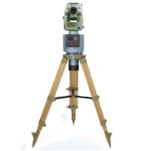
The gyro theodolite is a high-precision precision directional instrument that integrates light, machinery and electricity. It is widely used in various departments such as mining, construction, surveying and mapping, and military. Because it is not limited by time and environment, the observation is simple, convenient, and efficient, and it can ensure high accuracy. Therefore, it is an advanced directional instrument. Compared with traditional geometric orientation, gyro orientation has huge advantages. . However, due to design limitations and improper usage of domestic gyro power supplies, the repair rate of domestic gyro-theodolite purchased by most production units and many universities and research institutes has increased sharply. In view of the huge cost of going to the manufacturer for repairs and the fact that ordinary electrical repair personnel do not understand the principle of gyro orientation, the author has summarized the following gyro-theodolite maintenance procedures through repeated practice for reference by relevant units.


1.Common fault phenomena and maintenance logic

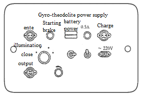
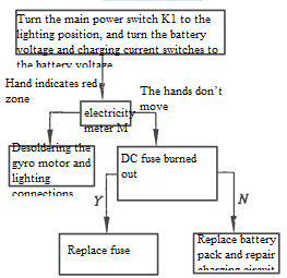
Fault phenomenon 1: The main switch K1 of the gyro power supply is placed in the lighting position and the starting position. The lighting light does not light up and the gyro motor cannot start (see Figure 1 for the gyro theodolite panel). See Figure 2 for maintenance logic.


Figure 1 Power box panel

Figure 2 Maintenance logic one


Fault phenomenon 2: Turn the main switch (K1) to the lighting position, the observation window light is on, but the gyro motor cannot start. See Figure 3 for maintenance logic.

Figure 3 Maintenance logic two


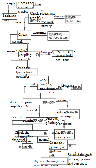
Fault phenomenon three: When the main switch is turned to the start position, the gyroscope can start, but the rotation speed is low and cannot be oriented. See Figure 4 for maintenance logic.

Figure 4 Maintenance logic three

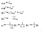
More than 90% of faults can be eliminated by following the above maintenance procedures. Although changes in the parameters of individual non-vulnerable components in the circuit can cause abnormalities in the instrument, the instrument can generally still work, and this phenomenon has not happened so far. As for the optical longitude and latitude of the instrument, when estimating the measurement method, all errors are considered to be equal and are all m, then

If the side length is set out, the relative error allowed is 1/T

2. Alignment error analysis

The analysis of alignment errors in "Engineering Surveying" is an analysis of an intermediate ruler section in a multi-foot section. The first and last sections each have only one alignment point, and there is alignment error only at one end, that is, there is no alignment error at points A and B (see Figure 2).

Summarize

Steel rulers are widely used to measure edges. In order to improve the accuracy of setting out and point accuracy, the prediction of measurement methods must be carefully carried out. In particular, accidental errors and systematic errors should be strictly distinguished when classifying. Otherwise, the prediction will be allowed. The error increases, and the requirements for engineering stakeout are relaxed, causing the point accuracy of the stakeout to fail to meet the requirements. Therefore, error prediction and measurement method prediction are the basis for meeting the point position accuracy stakeout. Only under this condition can the stakeout point position meet the accuracy requirements. ERICCO's gyro-theodolite is carefully preserved. If it encounters a malfunction, it will be repaired and operated according to strict requirements, such as ER-GT-02:

ER-GT-02 (≤3.6") Features:

  1. Orienteering accuracy ≤3.6" (1σ);
  2. Pit interference ability is strong, integrated fuselage design, compact structure, stable performance;
  3. Has the functions of low lock, automatic zero observation and etc.


If you want to learn about or purchase our gyro-theodolite, please contact our relevant technical staff.

Sunday, April 21, 2024

Analysis of Performance Index of Fiber Optic Gyroscope


1. Fiber Optical Gyroscope

The principle of fiber optic gyro is physically called Sagnac effect. In a closed optical path, two beams of light emitted from the same light source, relative propagation, confluence to the same detection point will produce interference, if the closed optical path has rotation relative to the inertial space, the beam propagating in the positive direction and the opposite direction will produce optical path difference, the difference is proportional to the upper rotation angular speed. The rotation angular velocity of the meter is calculated by measuring the phase difference of the photodetector.
Delta ∅ R = (2 PI LD/lambda c) * Ω
It can be seen from the formula that the longer the length of the fiber, the larger the light travel radius and the shorter the light wavelength. The more obvious the interference effect. Therefore, the larger the size of the fiber optic gyro, the higher the accuracy. The Sagnac effect is essentially a relativistic effect. It is very important for the design of fiber optic gyro.
The principle of a fiber optic gyroscope is that a beam of light is emitted from a photocell and passes through a coupler (1 end into 3 ends). Through the halo. Two beams enter the ring in different directions and come back around for a coherent superposition. The returned light is returned to the light-emitting diode and the intensity is detected by the light-emitting diode. The principle of fiber optic gyro looks relatively simple, but the most important thing is how to eliminate the factors that affect the optical path of the two beams. This is the most important problem facing doing fiber optic dras.

2. Principle of fiber optic gyroscope

At present, the most mature fiber optic gyro is the interferometric fiber optic gyroscope (I-FOG), that is, the first generation of fiber optic gyro, which is currently the most widely used. It uses multi-turn optical fiber coil to enhance SAGNAC effect. A double-beam ring interferometer composed of multi-turn single-mode optical fiber coil can provide high accuracy, but also will inevitably make the overall structure more complicated. Fiber optic gyros are divided into open ring fiber optic gyro and closed loop fiber optic gyro according to the type of loop. Open-loop fiber optic gyro without feedback, directly detect the optical output, save many complex optical and circuit structure, has the advantages of simple structure, cheap price, high reliability, low power consumption, the disadvantage is the input-output linearity is poor, small dynamic range, mainly used as an Angle sensor. The basic structure of an open-loop interferometric fiber optic gyro (IOFG) is a ring dual-beam interferometer. It is mainly used for occasions with low precision and small volume.

3. Fiber optic gyroscope performance indicators

Fiber optic gyro is to measure the angular speed, any measurement is error.

3.1. Noise

The noise mechanism in the fiber optic gyro is mainly concentrated in the optical or photoelectric detection part, which determines the minimum detectable sensitivity of the fiber optic gyroscope. In a fiber optic gyro, the random walk coefficient, which takes into account the detection bandwidth, is the parameter that characterizes the angular rate output white noise. In the case of white noise only, the definition of the random walk coefficient can be simplified as the ratio of the zero bias stability measured at a certain bandwidth to the square root of the detected bandwidth. If there are other types of noise or drift, the random walk coefficient should be obtained by fitting method, usually using Allan analysis of variance.

3.2 Zero drift (drift)

When using a fiber optic gyro, the Angle is used, which is obtained by integrating the angular velocity, and the cumulative error of any drift over a long time becomes larger and larger. In general, for fast response applications (short term), noise has a greater impact on the system, while for navigation applications (long term), zero drift has a greater impact on the system.

3.3 Scale factor (scale factor)

The smaller the scale factor error, the more accurate the rotation measurement will be.

4. Fiber Optic gyro future

4.1 High precision

Higher precision is an inevitable requirement for fiber optic gyro to replace laser gyro in high performance navigation. At present, the high precision fiber optic gyro technology is not fully mature.

4.2 High stability and anti-interference

Long-term high stability is also one of the development directions of fiber optic gyroscope, which can maintain navigation accuracy for a long time under harsh environment is the requirement of inertial navigation system for gyroscope. For example, in the case of high temperature, strong earthquake, strong magnetic field, etc., the fiber optic gyroscope must also have sufficient accuracy to meet the requirements of users.

4.3 Product diversification

It is necessary to develop products with different precision and different needs. Different users have different requirements for accuracy, and the structure of the fiber optic gyroscope is simple, and only the length and diameter of the coil need to be adjusted when changing the accuracy. In this respect, it has the advantage of surpassing mechanical gyroscopes and laser gyroscopes, and its different precision products are easier to achieve.

4.4 Production scale

The reduction of cost is also one of the preconditions for fiber optic gyro to be accepted by users. The production scale of various components can effectively promote the reduction of production costs, especially for middle and low precision fiber optic gyro.

5 Summary

Ericco fiber optic gyro ER-FOG-851ER-FOG-910 high precision, good performance, no wear parts, long life, low cost, is our long-term hot products, if you are interested in our products, want to get more technical data, please feel free to contact us.

Friday, April 19, 2024

Analysis of Technical Issues in Extending the Service life of Gyro Theodolite

https://www.ericcointernational.com/application/analysis-of-technical-issues-in-extending-the-service-life-of-gyro-theodolite.html

Ultra High Accuracy Gyro Theodolite

The gyro theodolite is a high-precision precision directional instrument that integrates light, machinery and electricity and is widely used in mining, construction, surveying and mapping, military, aviation, aerospace and other fields. Because it is not limited by time and environment, observation is simple, convenient and efficient, and it can ensure high accuracy, so it is an advanced directional instrument. Compared with traditional geometric orientation, gyroscopic orientation has huge advantages; compared with GPS global positioning system, it is not subject to electromagnetic wave propagation conditions and still has many advantages. Especially in production mine measurement, it is currently the most advanced directional instrument. However, due to some limitations in the design of domestic gyro-theodolite, most of the gyro-theodolite in most production units and colleges and universities in my country have been damaged to varying degrees, which not only increases the repair cost sharply, but also seriously affects production, teaching and research. In view of this, the author conducted research on how to improve the service life of the gyro-theodolite based on the principle and use experience of the gyro-theodolite, and improved some circuits to provide specific methods to extend the service life of the gyro-theodolite.

1.The composition and working principle of the gyro-theodolite

1∙1 Composition of gyroscopic theodolite


The gyro-theodolite consists of a gyroscope, theodolite, and an inverter power supply. The functions of each part are as follows:

Theodolite: Determination of direction value during orientation;

Gyroscope: Determination of true north direction when orienting;

Inverter power supply: Convert 24V DC power into 36V, 400Hz, three-phase medium-frequency AC power through the inverter circuit to drive the gyro motor to rotate at high speed to achieve orientation.


1.2 Working principle

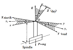
Suppose a gyro theodolite is set up on the earth's surface at a geographical latitude of , and point O is the intersection point between the gyro room and the suspension. With O as the origin, establish a coordinate system OXYZ fixed to the ground. The OX axis points horizontally to the north, and the OY axis points horizontally to the west. OXYZ rotates at the Earth's rotation angular speed of relative to the geocentric reference frame.At the same time, a moving coordinate system Oxyz fixedly connected to the gyro room is established at point O. The Ox axis is parallel to the main axis of the gyro. Looking in the forward direction counter to the Ox axis, the top rotates counterclockwise, and the angles are all counterclockwise. The meaning of angle is the deflection angle of the main axis relative to the meridian plane, the angle is the pitch angle of the axis relative to the horizontal plane, and the angle is the nutation angle of the gyro. The principle is shown in Figure 1.

Figure 1 Principle of gyro-theodolite gyro motion


2.Factors that restrict the service life of gyro theodolite and methods to extend its service life

From the working principle of the gyro theodolite, it can be seen that in order to measure the true azimuth angle of a certain side of the mine, it is necessary to observe the gyro movement for a long time. The gyro motor works in a high-speed rotation state. Therefore, the factors that restrict the service life of the gyro should be studied from the following aspects. consider.


2∙1 Instrument factors

The instrument factors that affect the service life of gyroscopes are mainly analyzed from the two aspects of gyro motor and inverter power supply. At present, most of the hanging gyros are used, which are relatively representative gyros in the world. They have their own characteristics in specific structures. . But the overall structure is basically similar. The core component of the gyroscope is the gyro motor, which is installed in a sealed, hydrogen-filled gyro room and hung up through a suspension strap. Two guide wires, a suspension strap and a bypass structure are used to power the motor. Therefore its structure is very compact. What is particularly important is that the suspension belt must not only withstand the torque of the gyromotor when it rotates at high speed, but also the weight of the gyromotor, as well as the passage of strong current. The complexity of the process can be imagined, so if you are not careful during use, will cause it to be damaged.


2∙2 Observer quality

Gyroscope operators should be trained in advance. On the one hand, they should ideologically strengthen their subjective awareness of caring for the instrument; on the other hand, their professional quality should be improved, especially so that they have an accurate understanding of the principles of the gyroscope. In this way, the operator will consciously operate according to the operating procedures during the instrument observation process, thereby reducing man-made damage to the instrument.


2∙3 Observation environmental conditions

As mentioned before, when the gyroscope is working, the gyro motor rotates at high speed, generating a large precession torque. At the same time, the motor's guide wire and suspension carry strong current through it, and the power amplifier part of the inverter power supply works with high current. state, so high heat will be generated in the gyro room and inverter power supply, causing the gyro motor and inverter power supply to heat up. In addition, the operation process takes a long time, so in high temperature weather and direct sunlight, the instrument is easy to burn and shorten the instrument. life.


It can be seen from the above analysis that the service life of the gyrotheodolite is restricted by many factors. If a certain link is not paid attention to properly, the instrument will be damaged. Therefore, operating the instrument reasonably and carefully and improving the efficiency of the inverter power supply are the keys to extending the service life of the gyro-theodolite. Based on many years of use experience, the author conducted corresponding theoretical analysis and research, and came up with the following specific methods to extend the service life of the gyro-theodolite:

(1) Operate the gyro-theodolite strictly in accordance with the operating procedures, which is the basis for ensuring that the gyro-theodolite is protected from accidental damage. The following points should be noted:

  1. The instrument must be used by personnel with certain operating experience who are familiar with the performance of the gyro-theodolite.
  2. Before starting the gyro motor to reach the rated speed and during the process of braking the gyro motor. The sensitive part of the gyro must be in a locked state to prevent damage to the suspension guide wire.
  3. When the sensitive part of the gyro is in a locked state and the motor is rotating at high speed, it is strictly forbidden to move or rotate the instrument horizontally, otherwise a large torsional force will be generated, compressing the bearings and damaging the instrument.
  4. Before turning on the gyro inverter power supply, check the connections repeatedly. When using an external power supply, pay attention to whether the voltage polarity is correct. Do not turn on the inverter when there is no load.
  5. When storing the gyroscope, put it in the instrument box and add desiccant. The instrument should be stored correctly and not placed upside down or lying down.
  6. When carrying out long-distance transportation, special shock-proof packaging boxes should be used.
  7. During summer or sunny weather observations, try to avoid direct sunlight on the instrument.


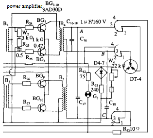
(2)Improve the high current and high voltage circuit part of the inverter power supply (the power supply circuit is shown in Figure 2).


Figure 2 Gyro inverter power supply circuit

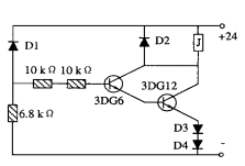
The cadmium-nickel battery of the inverter power supply is also an important factor that restricts the service life of the power supply. Nickel-cadmium batteries have a strict memory effect. In order to eliminate the memory effect, the author recommends using nickel-metal hydride batteries to replace nickel-cadmium batteries or installing a protection device on the gyro-theodolite discharger. To this end, the author designed a protection circuit for reference by each unit. The circuit is shown in Figure 3.

Figure 3 Principle of gyro discharger


Summarize

The above gives specific methods to extend the service life of the gyro-theodolite. Judging from the actual application results of this unit, it not only extends the

The service life of ERICCO can ensure the yield rate of experiments and save a lot of instrument repair costs. ERICCO's gyro theodolite includes ER-GT-03 Quick Gyro TheodoliteER-GT-05 Low Temperature Gyro Theodolite, and ER- GT-20 Portable Gyro Theodolite. They can be used in tunnel penetration measurement, subway engineering measurement, mine penetration measurement, and navigation equipment calibration. Our company has strict requirements for the preservation and use of gyro theodolite.


If you want to purchase a gyro-theodolite, please contact our relevant technical staff.

High-precision IMU is coming to help in the fields of land, sea and air

  High-precision IMU is now widely used in many fields of sea, land and air. It can provide real-time and accurate information on the carrie...