Showing posts with label precision tilt sensor. Show all posts

Monday, May 20, 2024

What can a Tilt Sensor be Used for?


Classification of angles

Angle measurement is an important part of geometric measurement. Plane angle according to the spatial position of the plane can be divided into: horizontal angle (or azimuth angle) in the horizontal plane, vertical right angle (or inclination angle) in the vertical plane, space angle is the synthesis of horizontal angle and vertical right angle; According to the range can be divided into circular indexing angle and small angle; According to the nominal value can be divided into fixed angle and arbitrary angle; According to the component unit can be divided into line angle and plane angle; According to the formation method, it can be divided into fixed angle and dynamic angle. Fixed angle refers to the angle of components processed or assembled, and the angular position of the instrument when it is restored to static state after rotation. Dynamic angle refers to the angle of the object or system in the process of motion, such as the angle of the satellite orbit to the earth's equatorial plane, the axis angle drift when the spindle of the precision equipment rotates, and the real-time angle signal output when the angle measuring equipment moves at a certain angular speed and angular acceleration.

What is another name for a tilt sensor

Tilt sensor is also known as the inclinometer, inclination sensor, level inclinometer, often used in the measurement of the horizontal angle change of the system, the level from the simple bubble level in the past to the electronic level is the result of the development of automation and electronic measurement technology. As a testing tool, it has become an indispensable and important measuring tool in bridge construction, railway laying, civil engineering, oil drilling, aviation and navigation, industrial automation, intelligent platform, mechanical processing and other fields. Electronic level is a very accurate measuring small angle detection tool, it can be used to measure the inclination of the measured plane relative to the horizontal position, the degree of parallelism between the two components and the degree of perpendicularity.

The basic principle of tilt sensor (inclinometer)

how does tilt sensor works

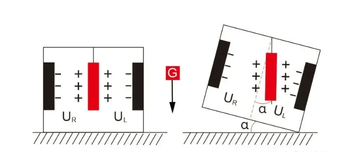
The theory is based on Newton's second law: according to the basic principles of physics, inside a system, velocity cannot be measured, but acceleration can be measured. If the initial speed is known, the line speed can be calculated by integrating, and then the linear displacement can be calculated, so it is actually an acceleration sensor using the principle of inertia. When the tilt sensor is at rest, that is, there is no acceleration in the side and vertical directions, then the only force acting on it is the acceleration of gravity. The angle between the vertical axis of gravity and the sensitive axis of the acceleration sensor is the angle of inclination. The tilt sensor in the general sense is static measurement or quasi-static measurement, once there is external acceleration, then the acceleration measured by the acceleration chip contains the external acceleration, so the calculated angle is not accurate, therefore, the common practice is to increase the mems gyro chip, and adopt the preferred Kalman filter algorithm. The ER-TS-3260VO's built-in (MEMS) solid pendulum can measure changes in the static gravity field, convert them into changes in inclination, and output them through voltage (0~10V, 0~5V optional), so that the calculated angle is quite accurate.

Use

Tilt sensors are used in a variety of applications to measure angles. For example, high-precision laser instrument level, engineering machinery equipment leveling, long-distance ranging instruments, high-altitude platform safety protection, orientation satellite communication antenna elevation measurement, ship navigation attitude measurement, shield pipe application, dam detection, geological equipment tilt monitoring, artillery barrel initial launch angle measurement, radar vehicle platform detection, satellite communication vehicle attitude detection and so on.

Application example

Used in tower cranes

The inclination sensor is the main part of the anti-overturning monitoring instrument of tower crane. The function of the inclination sensor is to measure the angle of the tower tilt in real time. Since the tilt angle at the top of the tower is very small, the sampling frequency of the tilt sensor should be within the range of 0.5-10Hz, the measurement accuracy is higher than 0.05 degrees, and the noise caused by the vibration of the tower should be filtered out to ensure reliable communication and accurate judgment. The accuracy of the ER-TS-3160VO Voltage Single Axis Tilt Meter is 0.01 degrees, which is obviously higher than 0.05 degrees, and it is suitable for the tilt monitoring in this case.

Thursday, April 25, 2024

Measurement of Moving Airfoil Deflection based on Wireless Tilt Sensor

 Based on the underlying measurement principle of the tilt sensor, considering the sensor system error, operation and installation error, and referring to the existing spatial Angle error analysis model, we improve the spatial Angle biaxis measurement error model suitable for the situation of moving airfoil deflection around the horizontal axis, and improve the calibration method according to the working condition. By using wireless transmission as a communication method, a complete set of moving wing deflection test system is built, which can display the Angle information of the moving wing in real time by visual means such as data, curves and three-dimensional models. The deflection Angle measurement accuracy is less than 0.05°, and the acquisition frequency is higher than 10 Hz, which can meet the actual measurement requirements.

Modern aircraft manufacturing mainly adopts modular assembly technology, the whole aircraft components in the assembly line to complete modular manufacturing and equipment installation test, and finally complete the docking of large parts on the final assembly pulsating production line to form the whole machine. For large aircraft, there are many types and quantities of movable airfoil, high profile accuracy requirements, many control and coordination links involved, large manufacturing and debugging workload, and complex installation and debugging processes.

The detection of deflection Angle is an important part of modular wing assembly test. There are many types and complex structure of the rudder surface of a certain key model, and the tilt sensor equipment installation of the traditional method of wing deflection Angle detection is cumbersome, the types of mechanical fixtures required are large, and the operation of workers is time-consuming and laborious. With the growing demand for various types of high-performance aircraft, the manufacturing tasks of aircraft manufacturers are increasing, and the production line needs an accurate, fast and real-time movable wing automatic inspection operating system that can reflect the production process in real time to improve the production line efficiency and ultimately increase the aircraft output.
At present, the commonly used methods to detect the deflection Angle of the active airfoil space include inertial measurement, laser tracker detection, visual detection, coordinate detection, multi-theodolite detection, linear displacement or angular displacement sensor indirect detection, mechanical protractor, etc. The methods are various, but all have certain shortcomings. Therefore, many studies have combined the above methods to improve the accuracy and applicability of measurement. The inertial measurement method based on tilt sensor is relatively portable, the measurement accuracy and efficiency can meet the actual demand, so we finally choose this method to test the deflection of moving airfoil.

System design and implementation

(1) A biaxial measurement error model is proposed for the scenario of the active airfoil deflecting around the horizontal axis. Considering the actual working conditions of the active airfoil deflecting, a new error variable is introduced to improve the calibration algorithm, so that the tilt sensor calibration algorithm can adapt to the special working conditions of the unparallel mounting surface. The calibrated sensor Angle output accuracy is improved, and the error is within the allowable range, which can meet the high precision testing requirements of the wing moving surface Angle.
(2) Complete the design and implementation of a large aircraft wing active wing deflection test system based on wireless communication protocol, and the field verification that it can achieve the mission objectives. Compared with the previous system, the hardware installation of the system does not need to connect wired communication cables, and the operation is simple. The calibration work can be automatically completed through software control, and the accuracy and real-time performance of data transmission under the wireless network can also be guaranteed, which can significantly improve the work efficiency of field active wing deflection test.
(3) Only installation errors were considered in the analysis of the measurement model of spatial Angle. In fact, there is coupling between all kinds of errors. In the subsequent research, we can try to identify all kinds of errors of the system as a whole to improve the measurement accuracy of the calibration model.

Summary

Ericco's two very popular wireless tilt sensors, ER-TS-12200-Modbus, accuracy can reach 0.001°, resolution 0.0005°, ER-TS-32600-Modbus accuracy moderate 0.01°, resolution 0.002°, you can choose according to your own needs, If you are interested in our wireless tilt sensors, please feel free to contact us.

Wednesday, April 10, 2024

Why and Where are Tilt Sensors Used


1. Why do people monitor tilt angles?

The world is constantly changing, and the tendencies of different objects and machines can provide insight into worrying trends and potential future problems. There are many reasons why people need to monitor the Angle or degree of inclination.

Avoid accidents and injuries
One reason is that it can help prevent injuries and avoid accidents. When people work on the slope, they need to pay attention to the Angle of the slope to ensure that they do not slip. If the Angle is too steep, it can cause an avalanche, which is very dangerous.

Ensure the normal operation of the device
Another reason to monitor the tilt Angle, or tilt, is to make sure the equipment is working properly. For example, if a machine is not level, it may not work properly. This can be dangerous for the person using the device and the people around it.

2. Where can the tilt sensor be used?

Tilt sensors can be used in many applications, such as the Marine industry, construction industry, infrastructure monitoring, etc.

Marine industry
Tilt sensors can be used on ships to measure ship roll and pitch. This information can be used to improve the stability of the ship and avoid capsizing.
Construction industry
In many construction machines, such as excavators and bulldozers, tilt sensors can be used to measure the Angle of the machine blade or bucket. This information can be used to automatically adjust the position of the blade or bucket, or to provide feedback to the operator.
Infrastructure monitoring
Tilt sensors can be used to monitor the status of infrastructure such as Bridges and buildings and alert authorities to potential hazards, such as leaning towers. By continuously monitoring the tilt of the structure, the sensors can detect even the smallest changes that could indicate a problem. In the event of a potential accident, sensors can provide critical information that can be used to evacuate people and take other safety measures.
Tree bend monitoring
Some trees may fall after storms, typhoons or other natural disasters. Tilt sensors can be installed at a certain height on these trees to monitor their x, y, and z values in real time. This can provide insights into tree tilt and movement and help make timely, effective decisions to protect trees and people.
Gate monitoring
In car parking lots and parking garages, the normal operation of road gates is crucial to the normal toll collection. The tilt sensor can be installed in the guardrail housing, especially suitable for the guardrail Angle measurement and movement detection, to determine whether the guardrail is dropped, bent or broken, if there is a trigger alarm, so that maintenance personnel can take measures in time. Ensure regular charges.

3. Summary

Ericco's ER-TS-12200-Modbus precision up to 0.001°, the use of advanced Internet of Things technology Bluetooth and ZigBee(optional) wireless transmission technology, all internal circuits are optimized design, using industrial MCU, three-proof PCB board, imported cables, wide temperature metal shell and other measures, Improve the industrial level of products. Good long-term stability, zero drift small, can automatically enter low-power sleep mode, get rid of the dependence on the use of the environment, equipped with IP67-rated housing, so that it can withstand harsh conditions and still work normally. The optimized internal design of multi-layer structure, sealing ring, and three anti-coating further enhances the waterproof and dustproof capability.

The ER-TS-3160VO voltage uniaxial tilt sensor is an analog voltage uniaxial tilt sensor. The user only needs to collect the sensor voltage value to calculate the tilt Angle of the current object. The built-in (MEMS) solid pendulum measures changes in the static gravity field, converts them into changes in inclination, and outputs them via voltage (0~10V, 0.5~4.5V, 0~5V optional). The product adopts the non-contact measurement principle and can output the current attitude and inclination Angle in real time. If you would like more technical data, please feel free to contact us.

Thursday, February 1, 2024

Stability Test and Analysis of Tilt Sensor


As a kind of angle measuring instrument, tilt sensor is widely used to measure the vertical angle of missile launching guide rail and the attitude measurement of engineering equipment.

In practical applications, the measurement focus of inclinometer sensor is stability measurement, so improving the stability of inclinometer sensor measurement becomes the most important thing. Because the external temperature has a great influence on the stability of the sensor, we focus on the test and comparative analysis of the working stability of the two tilt sensors in the field environment.
During the test, two inclinometer sensors using the same accelerometer were selected in the same field environment, and their starting characteristics, static stability and dynamic following were tested. Experimental data of the two sensors were collected and compared.

1. Sensor stability test
In the stability test of tilt sensor, according to the use of the tilt sensor on the installed equipment, this paper focuses on the test of the start-up characteristics, dynamic following and static stability of the tilt sensor. The measurement accuracy of the two inclinometer sensors selected for testing in this paper is 0.016°, and the inclination Angle of the test equipment is 60°. Before starting, the inclination sensor is in the horizontal state. The two tilt sensors selected during the test are named Sensor A and Sensor B.

1.1 Test Purpose
After a series of tests, the start-up, dynamic following and steady-state characteristics of the inclinometer sensor are obtained, which are easy to form charts for analysis.
1.2 Test Equipment 
The two inclinometer sensors selected in this paper are finished products, which are applied to the mechanical equipment to be tested as test equipment.
1.3 Test Environment
Because the test data obtained by the two sensors needs to be compared, the test environment of the two sensors is placed in the same place at the same time, that is, the test equipment is placed at the site where the device is used.
1.4 Test Platform
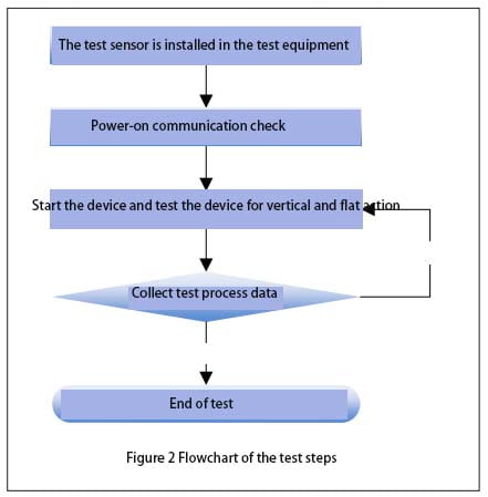
The tests were mainly conducted on two vertical devices. In the test process, firstly, the selected two inclinometer sensors are installed in the installation position of the test equipment and installed according to the sensor instructions; After that, power and communication checks are carried out on the inclination sensors to ensure that the two sensors can work normally. Finally, the test is carried out according to the test steps, and the output data in the whole process of sensor test is recorded.
1.5 Test Content
This paper mainly tests the starting characteristics, dynamic following and steady state characteristics of the two tilt sensors, that is, the normal use process of the test equipment. Since the entire process of using the sensor on the test device is tested, the test will be divided into three phases and conducted several times.
1.6 Test Procedure
The whole test process is relatively simple, and the test step flow is shown in Figure 2.
tilt sensor Flowchart of the test steps

1.7 Test data analysis
Since the inclinometer sensor is tested in a field environment, it is necessary to consider the temperature change of the environment. In this paper, the field environment temperature change curve is simulated as a sine curve, as shown in formula (1) :
f(t)=ksin((t×2π)/T) (1)
Where, t — time, the value is the test time point;
k — the difference between the highest and lowest temperature of the day, which in this paper takes the value of 24 ° C;
T — Time period, the value is 24 h. The test was conducted during the day, and the rate of temperature change was faster, so
We take the derivative of f(t). By substituting the values obtained in the test into the derivation formula, the fastest temperature change rate can be obtained, that is, 0.1 ℃/min.

1.71 Testing Startup features
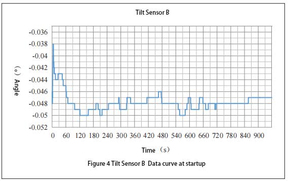
The equipment equipped with the inclination sensor is placed on the test site, and the measuring part of the sensor is placed in the horizontal state. At this time, the sensor is operated with power off. Power on the sensor two hours later and record the data generated within one hour after the sensor is powered on. Figure 3 shows the data curve of A and Figure 4 shows the data curve of B. It can be seen from Figure 3 that the Angle measurement value of A is 0.002° within 1 minute of power-on; The measurement value fluctuates from 0.001° to 0.002° and changes rapidly after 1 to 5 minutes of power-on. The measurement error is 0.001°. From 5 minutes to 14 minutes of power-on, the measured value fluctuates between 0.001° and 0.002°, while the fluctuation frequency is low, and the measurement error value is 0.001°. The measured value is stable after 14 minutes of power-on. It can be seen from the above that the Angle sensor selected in the test gradually stabilizes after 1 minute of power-on start-up. As can be seen in FIG. 4, the Angle measurement value of B is -0.048° after 15 minutes of power-on and start-up, the output measurement value reaches a steady state, and the measurement error value is 0.001°. The measurement value between 4 minutes and 15 minutes is -0.048°, and the measurement error is 0.002°. The measurement value between 1 minute 30 seconds and 4 minutes is -0.049°, and the measurement error value is 0.001°. The measured value is -0.048° within 1 minute and 30 seconds after power-on. The measurement error is 0.002° between 1 minute 30 seconds and 15 minutes after power-on and start-up, and then reaches stability.
The comparison between FIG. 3 and FIG. 4 shows that A reaches the stable state faster than B during power-on start-up; For A period of time after reaching stability, the measurement error of A is smaller than that of B.
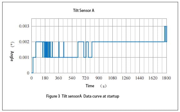
Tilt sensorA Data curve at startup

Tilt Sensor B Data curve at startup

1.72 Dynamic characteristic test
The Angle sensor is powered on and started. After the output measurement value is stable, the installation position of the vertical Angle sensor is raised. When the output data of the tilt sensor is obtained, the output measurement data of the sensor will be obtained to generate a curve. In addition, the parameters of device erection are obtained from the sensor mounting device, and the motion curve of the device erection is generated. The lag Angle data of the measured value of the sensor can be obtained by making A difference between the two curves. The lag curve of A is shown in Figure 5, and the lag curve of B is shown in Figure 6. As can be seen in Figure 5, the device is in a horizontal state before 35 s, and performs vertical action between 35 and 43 s. After 43 s, the sensor enters a stable state again. At 35 s, the device changes from a static state to a dynamic state, the hysteresis curve bulges downward, and the measured value of the sensor follows the device with good dynamic following. After that, the hysteresis of the sensor gradually increases, and the hysteresis reaches a maximum of 4.5° between 41 and 42 s. Finally, the Angle lag value becomes smaller and gradually becomes zero.
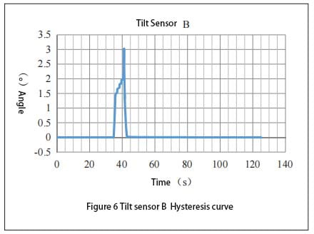
As can be seen from FIG. 6, the erecting process of B is the same as that of sensor A. When the device is erecting at 35s, the measured value of the sensor does not follow the sensor. After the device is erecting at A certain Angle, the measured value of the sensor will change the output, and the lag reaches a maximum of 3° between 41 and 42s. Finally, the angular lag value becomes smaller and gradually becomes zero.
The comparison between FIG. 5 and FIG. 6 shows that sensor A has better dynamic tracking performance than sensor B. When the lag between sensor and device reaches a certain degree, sensor B will use a new data processing method to improve sensor B’s tracking performance.
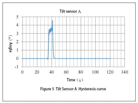
Tilt Sensor A Hysteresis curve

Tilt sensor B Hysteresis curve

1.73 Steady-state characteristic test
After the device is raised from the horizontal state to 60°, wait for the measurement data output by the inclinometer sensor to stabilize, continue to monitor and collect the sensor output data, and finish the test 5 to 6 hours later. The data generated during the steady state of the sensor is processed. The steady state curve of A is shown in Figure 7, and the steady state curve of B is shown in Figure 8. It can be seen from FIG. 7 that the output measured value of sensor A is relatively stable in the first 1 hour and 30 minutes. After 1 hour and 30 minutes, the measurement value began to shift to a large place, and reached a maximum value at 2 hours and 20 minutes, and then the deviation became smaller. At 4 hours it returns to its initial stable state again. Sensor A has a maximum offset of 0.007° when the temperature changes violently.
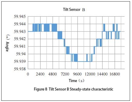
It can be seen from FIG. 8 that the output measured value of sensor B is relatively stable in the first 1 hour and 40 minutes. After 1 hour and 40 minutes, the measured value began to shift to a smaller place, and reached a maximum value at 2 hours and 30 minutes, and then the offset value became smaller. At 4 hours it returns to its initial stable state again. When the temperature change of sensor B is relatively drastic, the maximum offset of the measured value is
0.005°. Comparing FIG. 7 and FIG. 8, it can be concluded that under the same temperature change rate, the deviation of inclinometer sensor A is larger than that of inclination sensor B, and the measurement error of inclinometer sensor A is 0.001° larger than that of inclination sensor B. It can be seen that the steady-state characteristic of inclination sensor B is better than that of inclination sensor A.
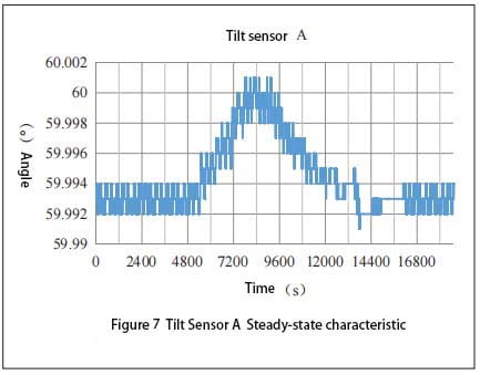
Tilt Sensor A Steady-state characteristic

Tilt Sensor B Steady-state characteristic

2 Summary
The starting characteristic, dynamic characteristic and steady-state characteristic of the inclinometer sensor are tested. Through comparative analysis of the test data, the starting characteristic and following characteristic of the inclination sensor A are better. The dynamic lag of inclination sensor B is small, and the Angle deviation is small in steady state and drastic temperature changes.
When we choose the inclination sensor suitable for the device’s use environment, such as ER-TS-12200-Modbus and ER-TS-32600-Modbus, we do not know which one to choose, we can conduct stability test and analysis on it according to the above method. According to the test data results to choose a more suitable one.  

RTK signal is easily blocked? IMU makes RTK have unlimited possibilities

When you use an RTK surveying instrument to measure in some places with obstructions or requiring a large tilt, do you always encounter weak...