Showing posts with label tilt sensors. Show all posts

Thursday, March 28, 2024

Large Outdoor Advertising Monitoring Based on Tilt Sensor

 When it comes to the use of tilt sensors to monitor angles, people's first reaction may feel very strange, in fact, we often use the mobile phone has a similar function, it is easy to search the relevant app in the mobile app store, and it is also very convenient to use, although there may be no one in the work really use the mobile phone as a measurement tool. But we can fully see that the measurement of the tilt Angle has been very easy.

At present, the inclination sensors used in many fields are basically based on MEMS (Micro-electro Mechanical System for short, Chinese name micro-electro-mechanical system) tilt sensors, around 1960, the United States took the lead in studying MEMS technology, Then France, Germany, Switzerland, Japan and other countries also began to pay attention to MEMS research work, China's MEMS research began in 1989, to 1999, China's domestic MEMS research and development units have reached more than 50, the level of scientific research can also be placed in the international top ten. As of 2010, there are about 600 units engaged in the research and production of MEMS in the world.
MEMS is an independent intelligent system, which integrates micro sensor, signal processing, actuator, interface circuit, control circuit, communication and power supply in one. It has the advantages of small size, low power consumption, light weight, strong durability, high stability, low price and easy mass production. It can be seen that MEMS refers to a system that is integrated by multiple devices. The current research on MEMS technology mainly includes: micro-mechanical pressure sensor, micro-gas sensor, micro-acceleration sensor, micro-flow sensor, micro-mechanical gyroscope, micro-mechanical temperature sensor and other micro-mechanical sensors.
Mems-based sensors have many uses, measuring tilt angle is just one of them, using acceleration sensors, such as gas flow measurement, temperature measurement, pressure measurement, and so on.
The application of MEMS technology to monitor the tilt angle of large outdoor advertisements is not a blind decision.

1. Monitoring methods for large-scale outdoor advertising
At present, there are four main monitoring methods for large-scale outdoor advertising:

(1) Camera monitoring
Due to the large outdoor advertising area is large, very eye-catching, mostly erected in bustling areas, highways and overpasses near, these geographical locations are also key jurisdiction areas of the city, therefore, these areas are basically covered by urban surveillance cameras, administrators can view large advertising and its surrounding situation through real-time monitoring. Although this monitoring method seems to have the characteristics of real-time, but it is difficult to achieve in practical applications, the monitor can not always stare at the surveillance video, and when the visibility is low, the effect of the surveillance video will be reduced a lot, affecting the observation of the monitor, therefore, the use of this method to monitor large-scale advertising is not ideal.

(2) Regular manual inspection
Surveyors field measurement is the most traditional monitoring method, the longest application time, the monitoring process is relatively mature,
This method is mainly used by inspectors to measure large advertisements using steel tape, optical theodolite, portable ultrasonic flaw detector, weld gauge, rebound meter and other equipment. Due to the support of high-precision data, this method has high credibility, but in order to achieve rapid and comprehensive monitoring of all large advertisements, not only need multiple sets of monitoring equipment. It also needs to use more manpower and material resources, which is very inconvenient, and this method is mainly preventive, which cannot achieve real-time understanding of large-scale advertising conditions, so this method is not ideal.

(3) Monitoring based on radio frequency technology
The technology is a non-contact automatic identification technology that emerged around 1990, which carries out non-contact two-way data transmission between the base station and the radio frequency card to achieve the purpose of identifying the target and data transmission. This method mainly uses 2.4GHz active radio frequency electronic tag to record the attribute information and location information of large advertisements. The electronic tag can sense the displacement, and a receiving base station is required to receive, process and transmit the data sent by the electronic tag. The technology is widely used in many fields such as small advertising management, highway ETC express lanes, logistics, retail and so on.
Although this method can obtain the position data of large advertisements in real time, it is not its strong point in monitoring the tilt Angle. This method can make up for the shortcomings of the above two methods, but the final result can not measure the tilt of large advertisements

(4) Sensor-based inclination monitoring
Tilt sensor is often used to measure the change in inclination relative to the horizontal plane, it is based on Newton's second law as a theory, according to the basic principles of physics, in a system, the speed can not be measured, but can measure its acceleration, under the condition of the initial speed is known, you can use the integral method to calculate the line speed, and then calculate the linear displacement. So it's an acceleration sensor that uses the principle of inertia. The tilt sensor is fixed on the back of a large advertisement, and the single chip microcomputer is used as the central controller to integrate the monitored angle data, monitoring time, monitoring site number and other information, and then through the General Packet Radio Service (GPRS), The wireless communication module will send out the packaged data, and the data will be analyzed and processed by the monitoring personnel, and this equipment is powered by solar energy + battery, making the equipment more independent and easier to manage. This method can understand the angle information of large advertisements in real time. In the case of investing very little manpower and material resources, you can fully understand the situation of each large advertisement, and the data credibility is high, so this way is more ideal.

2 Summary
In summary, after a more detailed analysis of various monitoring methods, it is not difficult to see that the method based on tilt sensors is the best to use this method to monitor the tilt of large-scale outdoor advertising. Ericco has various precision and types of tilt sensors, like ER-TS-3160VOER-TS-12200-Modbus, widely used in Bridges, DAMS, building monitoring and other fields, if you want to buy or want more technical data of tilt sensor, you can contact us at any time.

Tuesday, February 6, 2024

Analysis of Influencing Factors of Measurement Error of Tilt Sensor


1. Measurement accuracy of tilt sensor

The measuring accuracy is the measuring error range of the instrument. Measurement error and error is the basic problem of measurement test, any measurement will inevitably have measurement error, all the measured values are approximate values. Due to the influence of instruments, experimental conditions, environment and other factors, the measurement results can not be absolutely accurate, there will always be a large or small error between the measured value and the objective actual real value, and the range of this error is the accuracy of the measurement.
The tilt sensor has been used as an Angle measuring device to measure the relative sea level of objects for more than 100 years. From the traditional bubble type level, to the current acceleration principle or electrolyte principle and liquid capacitance principle, has been developed very mature, product accuracy continues to improve, the application field is gradually extensive and professional, manufacturers are also very many. However, the description of accuracy of most tilt sensors on the market is vague or there is a certain deviation. Generally speaking, according to the metrology law and relevant national/international standards, the description of accuracy has a general and deterministic description, but these descriptions are universal, whether they are suitable for the field of tilt sensors, there is no clear conclusion. First of all, we need to analyze the factors that affect the measurement accuracy of the tilt sensor, and then discuss how to determine the definition of the accuracy of the tilt sensor. Take the Angle sensor of acceleration principle as an example. It is the measurement of gravitational acceleration on the sensitive axis of the acceleration sensor into Angle data, that is, the Angle value and the acceleration value into a sine relationship. This principle is fully explained in many literature and product descriptions.

Factors affecting measurement error of tilt sensor

2. Indicators that affect the measurement accuracy of the inclinometer sensor

2.1 Sensitivity error - Sensitivity is used to describe the relationship between the input and output of the instrument, the input and output of the sensor are respectively used as the horizontal and vertical axis of the rectangular coordinate system, and the corresponding points of the ideal input and output values are connected into a curve, the slope of the curve is the sensitivity. The error value depends on the characteristics of the core sensor, but it is also related to the response frequency.

2.2. Zero bias - that is, when the input value is zero, the output value is not zero. The error depends on the characteristics of the core sensitive device itself, which means that in the case of the sensor without Angle input (absolute horizontal plane), the output Angle value measured by the sensor is not zero, and the output Angle value is zero offset.

2.3. Nonlinear error - the actual input and output value relationship curve does not coincide with the theoretical input and output value relationship curve, and cannot be made to coincide by translation, such errors are called nonlinear errors. The general expression method of its magnitude value is maximum error/range, that is, when the input reaches the maximum range, the output error is divided by the maximum range.

2.4. Horizontal axis error - refers to the error caused by coupling to the output signal of the sensor when the sensor applies a certain acceleration perpendicular to its sensitive axis or tilts at a certain Angle. For example, for a single-axis tilt sensor with a measuring range of ±30° (assuming that the X direction is the inclination direction of the inclination measurement), when a tilt of 10° occurs in the space perpendicular to the X direction (at this time, the tilt Angle of the actual measured X direction remains unchanged, such as +8.505°), The output signal of the sensor will cause an additional error due to this 10° tilt, which is called the cross-axis error. This extra error varies depending on the product. When the horizontal axis error of the inclinometer sensor is 3%FS, the additional error generated is 3%×30°=0.9°, and the actual output Angle of the sensor is simply estimated to be 9.405°(=8.505°+0.9°). At this time, even if the nonlinear error of the inclinometer sensor reaches 0.001°, relative to the horizontal axis error, this nonlinear error can be ignored, that is, as the measurement accuracy of the inclinometer sensor, the horizontal axis error cannot be counted, otherwise it will cause a large measurement error.

2.5. Allow the input shaft non-coincidence degree - refers to the sensor in the actual installation process, allow the sensor horizontal (Z direction) installation deviation, the index actually includes the input shaft non-alignment, vertical axis non-alignment error of two aspects. Generally speaking, the inclination direction of the inclinometer sensor is required to be parallel or coincide with the specified edge of the sensor when it is installed, which indicates that a certain installation Angle deviation can be allowed without affecting the measurement accuracy of the sensor. When the sensitive axis of the inclinometer sensor does not coincide with the actual tilt direction, the extra error is sinusoidal with the increase of the tilt Angle. The actual test shows that when the Angle between the sensitive axis of the inclinometer sensor and the actual inclination direction is more than 3°, for the linear error of the inclinometer sensor with the range of ±30° ±0.01°, the additional error will reach ±0.3~0.5°, which is much larger than the nonlinear error.

2.6. Repeated measurement accuracy - that is, when a value is repeatedly measured, the output value is not fixed to the same value, there will be random fluctuations, or in line with a random distribution. The error value depends on the characteristics of the core sensitive device and cannot be improved by subsequent correction measures.

2.7. Effect of temperature on zero point and sensitivity - also includes drift and repeatability of the temperature curve, which depends on the own characteristics of the core sensitive device and cannot be improved by subsequent correction measures. In the case of repeatability, it can be corrected later, depending on the number of correction points (Angle points and temperature points). The more correction points, the better the temperature drift accuracy.

3 Summary
It can be seen that the system errors of ER-TS-3160VOER-TS-4250VO and ER-TS-4258CU include sensitivity error, zero bias, repeatability and temperature drift repeatability, which cannot be corrected and compensated. Random error includes horizontal axis error, input axis misalignment, nonlinearity, temperature drift linearity, which can be improved by correction and compensation measures. Their resolution has nothing to do with accuracy, so they cannot be included in the accuracy index.
Therefore, the measurement accuracy of the inclinometer sensor must not be measured only by nonlinearity, and it is necessary to synthesize the systematic error and random error of the sensor. 

Thursday, February 1, 2024

ZigBee technology wireless transmission inclinometer sensor


ER-TS-12200-Modbus Features:

1. Dual axis monitoring (single axis optional);
2. Full range accuracy 0.001°, resolution 0.0005°;
3. Volume (94*74*64mm) (customizable).

Datasheet: https://www.ericcointernational.com/tilt-sensor/wireless-transmission-tilt-sensor/high-precision-wireless-transmission-tilt-sensor.html

Introduction
ER-TS-12200-Modbus High Precision Wireless Transmission Tilt Sensor is a wireless inclination sensor with ultra-low power consumption, small size and high performance, which is aimed at the industrial application of users without power supply or real-time dynamic measurement of object attitude angle. Powered by lithium battery, based on Internet of things technology Bluetooth and ZigBee (optional) wireless transmission technology, all internal circuits have been optimized and designed, and various measures such as industrial MCU, three proof PCB board, imported cable, wide temperature metal shell are adopted to improve the industrial level of the product. With good long-term stability and small zero drift, it can automatically enter the low-power sleep mode, so as to get rid of the dependence on the use environment.
The product has compact structure, precise design, recompensation for temperature and linearity, and integrated comprehensive protection functions such as short circuit, instantaneous high voltage, polarity, surge, etc. it is simple and convenient to use. The wireless digital signal transmission method eliminates the cumbersome wiring and noise interference caused by long cable transmission; The industrial design has extremely high measurement accuracy and anti-interference ability. The wireless sensor nodes can form a huge wireless network, support thousands of measuring points to monitor the inclination at the same time, and support professional computer software. Without field survey, it can measure and record the state of the measured object in real time; The safety monitoring system is suitable for remote real-time monitoring and analysis of industrial sites, dilapidated houses, ancient buildings, civil engineering, tilt deformation of various towers and other needs.

Features
Dual axis monitoring (single axis optional)
Range: ±30°
Accuracy: 0.001°, resolution: 0.0005°
Volume (94*74*64mm) (customizable)
Ultra low power consumption
Powered by built-in rechargeable lithium battery
Wide temperature operation -40~+85℃
IP67 protection grade

Applications
Bridge construction
PTZ levelling
Ship navigation attitude measurement
High railway foundation tunnel monitoring
Satellite solar antenna positioning
Medical equipment
Angle control of various construction machinery

Tuesday, January 30, 2024

How to Improve Reliability of Tilt Sensors


 1. How to ensure the reliability index of the tilt sensor

For the technical indicators and performance indicators of the tilt sensor, there are usually clear and quantitative index requirements, which can be directly measured and tested when the product leaves the factory. For reliability indicators, it is generally impossible to implement direct measurement and inspection, and it is necessary to carry out reliability design and control of the whole process of product development and production to ensure that the reliability indicators meet the requirements. We mainly discuss the reliability supervision and control, design and evaluation and test of tilt sensor in the development, production and use stage.

2. Reliability design
The development stage of inclinometer sensor can be divided into demonstration stage, scheme stage, development stage and finalize stage. According to the technical requirements of the tilt sensor, the MTBF task value θS of the sensor is determined in the demonstration stage, and the θS is preliminarily demonstrated according to the reliability level of the sensor product.
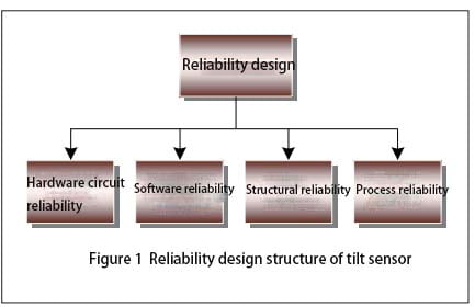
When the inclinometer sensor is in the project stage, it is necessary to design according to the tactical technical index of the inclination sensor and work out the functional block diagram of the sensor. According to the block diagram of tilt sensor, the internal logic relationship in the block diagram is analyzed, and the reliability block diagram of the newly developed inclination sensor is compiled. According to the reliability block diagram of the inclinometer sensor, the reliability indicators are assigned to each subsystem of the sensor, or the reliability indicators on the technical requirements are weighted, and the results after allocation must meet the reliability indicators of the whole system. After the reliability block diagram is prepared and the reliability index is assigned, the estimated reliability value θP is estimated for the components used in the hardware circuit. According to the obtained θP value, the part of the hardware circuit that affects the reliability of the sensor is designed and changed. At last, the functional block diagram, reliability block diagram, reliability distribution index and reliability predicted results prepared according to the technical requirements of the inclination sensor are reviewed periodically in order to improve the design of the defects that affect the reliability of the sensor. In the reliability design of the tilt sensor, the design needs to be considered as shown in Figure 1.

Reliability design structure of tilt sensor

2.1 Reliability design of hardware circuit
After the inclinometer sensor enters the development stage, the hardware circuit is designed according to the functional block diagram and reliability block diagram.
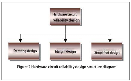
In the design of hardware circuit reliability, the aspects that need to be considered are shown in Figure 2.

Tilt sensor Hardware circuit reliability design structure diagram

In the process of hardware circuit design, components are the basis of circuit reliability design. In the actual sensor hardware circuit, due to different environments, load changes and a series of reasons such as the design of the sensor drift fault, therefore, in the actual design of the hardware circuit should be integrated into the margin design, after the completion of the hardware circuit design, before the data transmission, it is required to check the integrity of the components in the hardware circuit to ensure that the sensor is powered on. Correct and intact data transmission between each unit. In addition, limit testing and reasonableness testing are performed on all analog and digital inputs and outputs in the hardware circuit.
2.2 Software program reliability design
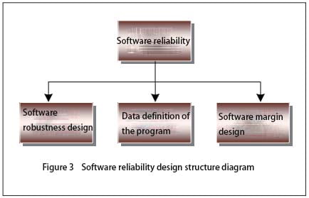
In the design of the hardware interface software of the sensor, the failure detection of the external input or output device must be considered first, and when the failure is detected, the software can restore the interface to a certain safe state, and the hardware failure mode involved is also required to be considered. When the sensor transmits data, in order to ensure the authenticity and reliability of the data received by the receiver, the data sent by the sender is required to use a specific format and content, so that the sender and the receiver can use the agreed method for verification. In the process of software design, its reliability design structure is shown in Figure 3.

Tilt sensor Software reliability design structure diagram

When the software program of the sensor is written, the first thing to consider is the robustness of the software. In software robustness design: First, the power module of the inclinometer sensor may have intermittent failure at the moment of power supply, so that the inclinometer sensor into a potential unsafe state, in order to avoid this state, it is required that the software safely shut down the sensor when the sensor power supply fails, in addition, the power supply of the inclination sensor may have abnormal fluctuations. Software is also required to handle it; Second, the software design must take into account a self-test when the sensor is powered on, verifying that the sensor system itself is safe and can operate normally, and when necessary, the sensor can carry out periodic self-testing; Third, the inclination sensor needs to work normally in electromagnetic radiation, static interference and other environments, which requires the sensor hardware circuit design to be processed according to the technical requirements, so that the sensor can control the external interference within the specified range, when there is external interference, the software is reset again, so that the sensor can still operate normally. Secondly, it is necessary to carry on the margin design when writing the sensor operation program. While ensuring the storage capacity and data channel transmission capacity of each module of the software, the software margin of the inclination sensor should be planned to ensure that the software margin meets the requirements. According to the specific state of each subsystem during software running, the arrangement of various cycles and working time series of software is determined to ensure that sufficient margin is reserved between software working time series.
Finally, consider the data definition when the sensor program is written. When defining the data in the software operation process, it is necessary to ensure that the defined data must be within a reasonable range, so that the sensor can ensure the size and error of the value within the specified range during the data operation process to ensure the accuracy of the data operation. In addition, reasonableness checks are also carried out at the entrance, exit, and other key locations of the software.
2.3 Structural reliability design
In addition to the protection of the external environmental stress, the electromagnetic compatibility of the inclinometer sensor is mainly optimized in the structure of the sensor. Under modern conditions, electromagnetic interference is everywhere, in this environment to make the sensor normal operation, it is required to optimize the sensor in hardware circuit, overall structure, manufacturing process, etc., in order to reduce the sensitivity of the sensor for interference, so that the external entry and internal leakage of electromagnetic interference can be controlled in a acceptable range.
2.4 Process reliability design
Process reliability design is mainly divided into printed board reliability design, electrical interconnection design and “three defenses” design. The reliability design of the printed circuit board requires the layout of the entire circuit board to be reasonable, and a single functional module or functional circuit is placed on a panel as far as possible, which is more convenient for later troubleshooting and maintenance. The circuit board should be rationally arranged on the circuit board, the circuit at all levels should be arranged and combined according to the distribution of the schematic diagram, the input and output of the sensor should be arranged separately, the analog circuit module and the digital circuit module should be isolated, the layout and wiring should be reasonable as far as possible, and the generation of parasitic coupling electromagnetic interference should be suppressed. When placing electronic components on the circuit printed board, it is required to be as suitable as possible for visual inspection of the entire circuit printed board, to facilitate the inspection of the nominal value of electronic components and fault location. When placing large and heavy components on the circuit printed board, it is necessary to reinforce them to prevent damage to components caused by vibration and impact of the sensor and make the sensor unable to operate normally. The design of electrical interconnection requires the sensor process specification to specify the installation and welding temperature and time of the components, the welding specifications of the inserted components and the operating conditions of the welding operators. The “three defenses” design requires the developer to fully understand the use environment of the sensor, master the characteristics of the sensor use environment and the law of change, analyze the stress conditions of the sensor failure in its use environment, and finally choose the suitable defense for the sensor
Enclosures, materials and sensor manufacturing processes.
3 Summary
By analyzing the reliability of inclinometer sensors in the process of development, production and use, we integrate the reliability design of wireless ER-TS-12200-Modbus and single-axis ER-TS-3160VOER-TS-4150VO and other tilt sensors into the development and production of sensors. Through the reliability information collected by customers during the use of such products, the reliability assessment of the sensor is carried out, and the reliability improvement of the tilt sensor is finally completed. 

Monday, January 29, 2024

Tilt sensors are booming


Introduction

ER-TS-3160VO Voltage Single Axis Tilt Meter is an analog voltage single axis tilt sensor. Users only need to collect the sensor voltage value which can calculate the current object tilt angle. The built-in (MEMS) solid pendulum measures the change of static gravity field, which is converted into the change of inclination, and the change is output through the voltage (0~10V, 0.5~4.5V, 0~5V optional).
The product adopts the non-contact measuring principle, which can output the current attitude and inclination angle in real time. The operation is simple, there is no need to look for two faces with relative changes. It has the characteristics of small size and strong shock and vibration resistance, especially suitable for harsh industrial environments.

More details: https://www.ericcointernational.com/tilt-sensor/single-axis-tilt-sensor.html

Features
Single axis tilt monitoring
Full range accuracy 0.01°, resolution 0.001°
Output 0~5V, 0.5~4.5V, 0~10V (optional)
Wide voltage input DC 9~36V
Wide temperature working -40~+85℃
Measuring range: 0~±180° (optional)
High vibration resistance>20000g
IP67 Protection
Can output RS232 at the same time, RS485 optional
Small volume (90*40*27mm) (customizable)

Applications
Railway gauge ruler, gauge instrument
Satellite solar antenna positioning
High altitude working vehicle
Mining machinery, oil logging equipment
Medical equipment
Tripod head levelling  
Hydraulic lifting platform
Inclination monitoring
Angle control of various construction machinery
Inspection of bridges and dams

Tuesday, January 23, 2024

Application of Tilt Sensor in Vehicle Four-wheel Positioning


Article details: https://www.ericcointernational.com/application/application-of-tilt-sensor-in-vehicle-four-wheel-positioning.html

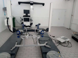
Tilt sensor in the four-wheel locator

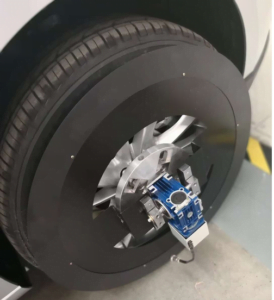
For different four-wheel positioning equipment, the key role is to measure the accuracy of the tilt sensor. Modern cars generally adopt front and rear independent suspension, and the main parameters detected by the four-wheel alignment instrument are wheel camber, kingpin rear angle, kingpin internal angle and front bundle. For the measurement of the above tilt angles, except the front beam angle is generally realized by the rotary disk or the angle sensor, and the other angles are generally adopted by the tilt sensor. The tilt sensor is fixed on the four-wheel alignment mounting plate, and then installed on the wheel of the car through the clamp.

Due to the reason of automobile structure, the tilt measurement of automobile wheel positioning angle is divided into direct measurement and indirect measurement. From the definition of wheel inclination, it can be seen that the measurement of wheel camber can be measured directly by the tilt sensor, while the kingpin internal inclination and kingpin rear inclination are not, because the kingpin is installed on the inside of the wheel, generally can not be measured directly by the tilt sensor. The measurement range of wheel inclination should be about ±15°. In today’s models, the inclination adjustment deviation value is generally about 5′, such as: Shanghai Volkswagen PASSAT B5 front wheel camber value is -0°35′ to ±0°25′, so the sensor measurement resolution should be less than or equal to 5′.

Application of Tilt Sensor in Vehicle Four-wheel Positioning

What is car four-wheel positioning?

From the structure of the car, the car’s steering wheel (front wheel), steering knuckle and front axle installation between the three has a certain relative position, this installation with a certain relative position is called steering wheel positioning, also known as front wheel positioning. Front wheel positioning includes

Kingpin back tilt (angle), kingpin inward tilt (angle), front wheel outward tilt (angle) and front wheel front bundle four contents. For the two rear wheels, there is also a relative position between the installation and the rear axle, called the rear wheel positioning. Rear wheel positioning includes wheel roll out (angle) and one rear wheel front bundle. In this way, the front wheel positioning and the rear wheel positioning are called four-wheel positioning.

When the vehicle leaves the factory, the positioning angle is pre-set according to the design requirements. These positioning angles are used together to ensure the driving comfort and safety of the vehicle. However, because the vehicle is sold and driven for a period of time, these positioning angles will change due to traffic accidents, severe bumps caused by uneven road potholes (especially when driving at high speed suddenly encounter uneven roads), chassis parts wear, chassis parts replacement, tire replacement and other reasons. Once the positioning angle changes due to any reason, it may produce uncomfortable symptoms such as abnormal tire wear, vehicle deviation, reduced safety, increased fuel consumption, accelerated wear of parts, heavy direction, and vehicle drift. Some symptoms make the vehicle very dangerous at high speeds.

Application of Tilt Sensor in Vehicle Four-wheel Positioning1

What is a four-wheel locator?

The purpose of four-wheel positioning maintenance service is to diagnose and treat the above causes of vehicle discomfort by measuring the positioning Angle. Generally, the new car should be four-wheel positioning after 3 months of driving, and every 10,000 kilometers after driving, replacing the tire or shock absorber, and after the collision should be timely four-wheel positioning. The correct positioning of the wheel can ensure that the steering is flexible, the seat is comfortable, the straight line driving is maintained, the life of the tire is extended, and the vibration caused by the road is reduced.

At present, most of the instruments used for wheel positioning detection are “four-wheel positioning instrument”. During the detection, the four-wheel positioning instrument first measures the current four-wheel positioning parameters of the car, and then the computer automatically compares it with the stored value of the corresponding model to calculate the deviation value of the four-wheel positioning of the car, and the maintenance personnel can restore the original state by correcting the prompts of the positioning instrument.

In Summary:

Ericco introduces the ER-TS-4256DI1, a tilt sensor for automotive four-wheel aligners, which has multiple interfaces and can be easily embedded into user systems. It can resist external electromagnetic interference, adapt to the harsh industrial environment for long-term work, is the ideal choice for industrial automation control and platform attitude measurement. The main features are as follows:

Biaxial dip measurement (X and Y) 

Resolution less than 0.01°, accuracy 0.1°

Single PCB board, easy to embed into the user circuit system

Single power supply, digital signal (RS485) output

Built-in temperature sensor (digital SPI output)

Vibration resistance 3500g  

Thursday, January 18, 2024

Research on Angle Control Technology of Tilt Sensor


Why introduce tilt sensors to form a closed-loop control system?

How to calibrate the inclinometer sensor and connect it to the coordinated loading control system becomes the key to solve the following problems.
In the traditional structural strength test, the coordinated loading control system mainly controls the load and displacement. Its core control unit belongs to closed-loop negative feedback regulation, and PID control is commonly used in engineering. However, in the loading process of an aircraft structure strength test, it is required to test the performance characteristics of a moving mechanism while the mechanical load is loaded, but the regulator of the mechanism belongs to open loop control, and it cannot be measured effectively and accurately during the loading process. This requires the introduction of inclinometer sensors in the actual loading process to form a closed-loop control system to achieve accurate Angle control. Therefore. In this paper, the signal parameters of tilt sensor are studied and tested, and the calibration method of sensor feedback signal and the method of signal participating in closed-loop control are proposed to realize real-time Angle measurement and control of the moving mechanism of test piece.

1. The way the inclination sensor is connected to the coordinated loading control system
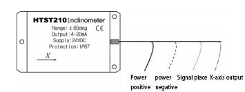
In the strength test of a new type of structure, it is necessary to apply mechanical load while coordinating the loading control system can synchronously monitor the Angle change of the moving mechanism of the test piece, that is, the Angle change between the measuring surface and the horizontal plane. Therefore, the inclination sensor is introduced in the test for the Angle monitoring of the moving mechanism of the test piece. The inclination sensor is shown in Figure 2.

tilt sensor

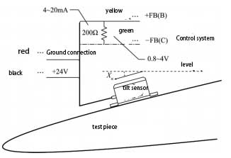
The output signal of the inclination sensor is DC analog signal, which needs external 24V DC excitation power supply in normal operation. The excitation power supply provided by DC voltage regulator power supply is used as the excitation power supply of the inclinometer sensor in the test. After research, there are two ways to connect the output of the inclination sensor to the coordinated loading control system. One is to transform the sensor connection mode of the coordinated loading control system and access it from the sensor channel panel; the other is to use the BNC connector to access it from the analog input channel. We test Angle parameters to participate in closed-loop control, so choose the first access mode. In addition, since the channel input of the control system recognizes the DC voltage signal, the output signal of the inclination sensor needs to be converted before it is connected to the control system. A precise resistor is connected at the output end of the inclination sensor to convert the output signal of the inclination sensor from current signal to voltage signal. The access control system is shown in Figure 2.

tilt sensor-Access control system

2 Calibration method
Since the voltage signal is an analog signal, it is necessary to calibrate the voltage signal after it is connected to the control system, that is, the corresponding relationship between the output voltage value of the inclination sensor and the actual Angle value is determined by adjusting the channel gain, △k, zero point, unit and other parameters, and ensure that the reading result of the control system is consistent with the actual Angle when the actual Angle is changed. There are two ways of calibration, respectively to test it, the process is as follows.

2. 1 Zero gain method
Firstly, a precision resistor with a fixed resistance value of 200Ω is connected at both ends of the output signal line of the inclination sensor, so that the DC current signal output by the inclination sensor becomes the DC voltage signal that the control system can recognize. The signal output range of the inclinometer sensor is: 4 ~ 20 mA, and the corresponding voltage signal range is: 0.8 ~ 4 V. The maximum voltage range allowed by the coordinated loading control system is -10 ~ 10 V. The signal gain of the input channel can be calculated according to the following formula.

tilt sensor zero gain formula

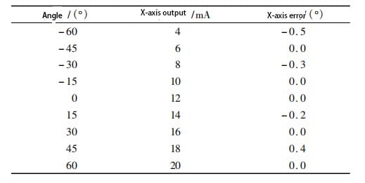
Input this gain into the analog signal channel, and then place the inclination sensor horizontally. Refer to the following table to obtain the current value corresponding to the output of the inclination sensor when it is placed horizontally, and then convert it to the voltage value. Then adjust the zero point to make the voltage displayed by the control system this voltage value.

Single-axis tilt sensor test results

2. 2 Calculate the channel method
The Angle θ of the inclinometer sensor and the X axis output x are linear, that is, θ = k × x + b
Referring to the specific values in the table above, the least square method can be used to determine the linear relationship between the Angle θ(°) and the X-axis output x(mA), that is, to determine the k and b values. As with the gain method, a precision resistor with a fixed resistance value of 200Ω is connected at both ends of the output signal line of the inclinometer sensor, so that the DC current signal output by the inclination sensor becomes the DC voltage signal that the control system can recognize. Finally, the voltage feedback signal V of the inclination sensor monitored by the control channel is assigned to a calculation channel, and the corresponding Angle value can be obtained by editing the voltage feedback signal of the control channel into the following formula through the formula editor module of the calculation channel:

tilt sensor voltage feedback formula

When the unit of the computing channel is set as the Angle, the real-time monitoring of the Angle can be realized through the computing channel. The zero gain method and the calculation channel method are used to calibrate the two inclination sensors respectively, and the results are consistent with the actual Angle, which proves that the two calibration methods are feasible.
3. Test and verification
In the strength test of a new type structure, the deflection Angle of the moving airfoil is measured and controlled by introducing an inclination sensor.
3. 1 Test system construction
The inclination sensor is attached to the active airfoil, and the output axis X axis is perpendicular to the deflection direction of the active airfoil, which is used to measure the deflection Angle of the active airfoil relative to the horizontal plane. The measurement signal is connected to the coordinated loading control system through either of the above two access methods. The inclinometer sensor is pasted as shown in Figure 2.
The Angle deflection of the movable airfoil is driven by the rotation of the steering wheel and the deflection of the movable airfoil through the hydraulic swing cylinder installed in the cockpit. The hydraulic swinging cylinder is fixed to the driving disc, and a torque sensor is installed between the two to monitor the torque during the rotation of the driving disc driven by the swinging cylinder; The rear end of the hydraulic swing cylinder is connected with an angular displacement sensor to measure the rotation Angle of the steering wheel in real time. The signals of the torque sensor and the angular displacement sensor are simultaneously connected to the coordinated loading control system for monitoring or control, and the output control signal of the control system controls the opening size of the servo valve to achieve accurate control of the deflection Angle of the movable airfoil.
Should note:
① The angular displacement sensor and the hydraulic swing cylinder are fixed connected, and the rotating shaft has no relative rotation;
② The rotation axis of the angular displacement sensor, hydraulic swing cylinder and torque sensor should be in the same straight line and remain level on the horizontal plane.
3. 2 Test Method
Coordinated loading control system, hydraulic swing cylinder and angular displacement sensor constitute closed-loop control. The command given by the control system is the rotation Angle command of the steering wheel, and the control cylinder drives the steering wheel to rotate, so as to realize the Angle deflection of the movable airfoil; The inclinometer sensor only acts as the Angle measurement and monitoring of the active airfoil, and calculates and monitors the Angle of the active airfoil in real time through the computing channel.
3. 3 Test results and analysis
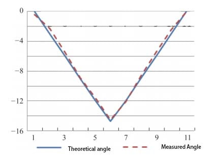
The test adopts method one to control loading, the results show that the Angle control can be realized, and the control accuracy meets the requirements of the test. The angular deflection results of the movable airfoil are shown in Figure 3.

tilt senor-The result of the angular deflection of the movable airfoil

4 Summary
The technique has been successfully verified in the control test of a certain type of aircraft elevator (rudder surface with load). Ericco’s ER-TS-3160VO and ER-TS-4158CU are two hot-selling tilt sensors of voltage and current type. They can access the control system from the sensor channel panel by modifying the sensor wiring mode of the coordinated loading control system. Because the input end of the control system’s channel recognizes DC voltage signals, Therefore, before the sensor output signal is connected to the control system, the output signal needs to be converted. A precise resistor is connected at the output end to convert the output signal from current signal to voltage signal. By using the test system, the deflection degree of the moving airfoil is controlled while the mechanical load is applied to the moving airfoil. The test system can be further improved and optimized, so that the control quality is higher and the application range is wider. 

Tuesday, January 16, 2024

Research on Temperature Characteristics of Tilt Sensor


1. Influence of temperature on tilt sensor

Tilt sensor is widely used in various angle measurement, such as high precision laser instrument level, ship navigation attitude measurement, geological equipment tilt monitoring, satellite communication vehicle attitude detection. However, in the harsh working environment, the inclination sensor is easily affected by temperature, and there are zero point and sensitivity temperature drift.
Because the temperature of the working environment of the tilt sensor changes greatly, and the heat output caused by the temperature change will bring large measurement errors. At the same time, temperature changes also affect the size of zero and sensitivity values, and then affect the static characteristics of the sensor, so measures must be taken to reduce or eliminate the impact of temperature changes, that is, temperature compensation must be carried out.

2. Tilt sensor temperature compensation method
Inclination sensor temperature compensation methods are generally divided into hardware compensation method and software compensation method. Hardware compensation method is mainly achieved by changing device structure, material, working environment and technology to improve the reliability of measurement results. But in practical application, the working environment is bad, the structure of hardware compensation method is complicated and it is difficult to achieve the ideal effect. The idea of software compensation is to separate and compensate the error through experiment. Because the temperature error of tilt sensor is a nonlinear error, it is difficult to achieve a high compensation accuracy. RBF neural network has strong curve fitting ability. Compared with BP neural network, we use RBF neural network for temperature compensation of inclinometer sensor, which greatly reduces the influence of temperature on tilt sensor and achieves good compensation effect.

3. Temperature compensation based on radial basis function RBF neural network
3.1 RBF neural network compensation principle
RBF neural network is a kind of forward feedback-free network with excellent performance. It can approximate continuous function with arbitrary precision and has been widely used in pattern recognition, function approximation and so on. RBF neural network is composed of input layer, hidden layer and output layer. The hidden layer nodes are composed of Gaussian radial basis functions, as shown in equation (1) :

tilt sensor-Gaussian radial basis function

i=1,2,…,h (1)Where: ci is the center of the i-th basis function and has the same dimension as x; σi is the extension constant or width of the i-th basis function, and the smaller σi is, the smaller the width of the radial basis function and the more selective the basis function is. Neurons in the output layer adopt a linear activation function, and the output of the KTH neuron is shown in equation (2) :

Tilt sensor-output of the KTH neuron

Where: yk is the output of the KTH neuron in the output layer; W2ik is the connection weight of the I-th neuron in the hidden layer and the K-th neuron in the output layer.
In the parameter design of RBF neural network learning algorithm, it is generally necessary to design three parameters: data center of each basis function, expansion constant and weight of output node. We use K clustering algorithm to determine the basis function of the data center. Recursive least square method is used for the weight between hidden layer and output layer to ensure faster convergence speed.

3.2 RBF neural network temperature compensation results
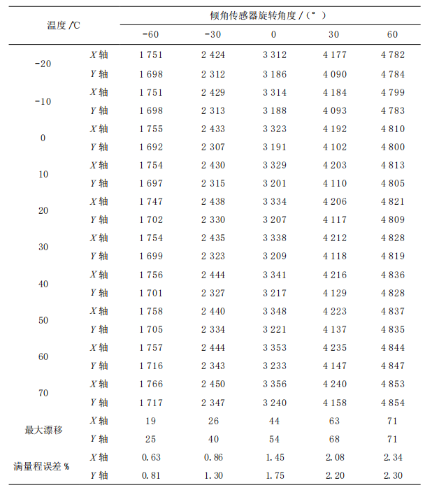
In the simulation experiment, the output value T1 of the inclination sensor and the temperature of the temperature box are taken as the input of the model, and the rotation Angle of the tilt sensor is taken as the output of the model. The 100 sets of data in the following table are samples of the RBF neural network two-input-output model.

Tilt sensor temperature experiment data recording

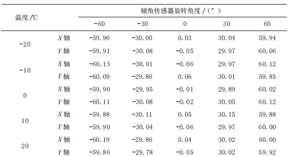
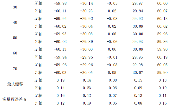
The input layer of the neural network is composed of two neurons, and the output layer is composed of one neuron. The number of hidden layer neurons is automatically added by the software through checking the output error until the error requirement or the maximum number of hidden layer neurons is reached. Through several experiments, the radial basis function distribution density SPREAD=0.5 and the training target error was set as EGOAL=1e-6. After 25 training sessions, the target training accuracy was achieved. Compensation results are shown in the following table.

tilt sensor-RBF neural network temperature compensation results1

tilt sensor-RBF neural network temperature compensation results

The output RBF neural network modeling graph is shown in the following figure

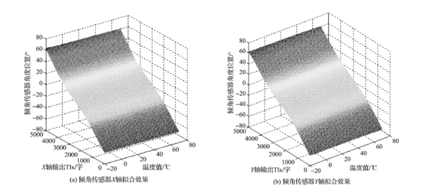
tilt sensor-Neural network fitting effect

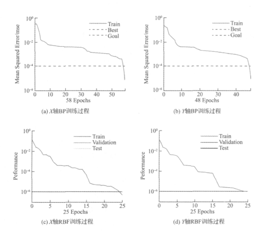
Comparing Table 1 and Table 2, it can be seen that the temperature drift and full scale error of each axis are greatly reduced after modeling by RBF neural network. As can be seen from the RBF network fitting effect diagram in FIG. 3, the simulation graphics transition smoothly at each point, and the model compensation effect is relatively ideal. In order to compare the compensation effect of the RBF network, we also set up the BP neural network compensation model which is often used for temperature compensation. The input layer of BP neural network is composed of two neurons and one implicit layer. After many experiments, it is determined that the optimal number of hidden layer is 5, and the output layer is composed of 1 neuron. The goal error of the training is EGOAL=1e^(-4), and the learning efficiency is LP.lr=0.2. In the experiment, 100 groups of samples in Table 1 were used to train the established BP network. After about 50 iterations, the training was completed. The training pairs of RBF and BP network were shown in the following figure.

Tilt sensor-Comparison of RBF and BP neural network training

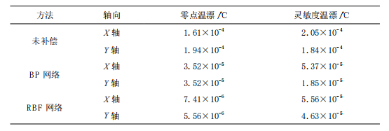
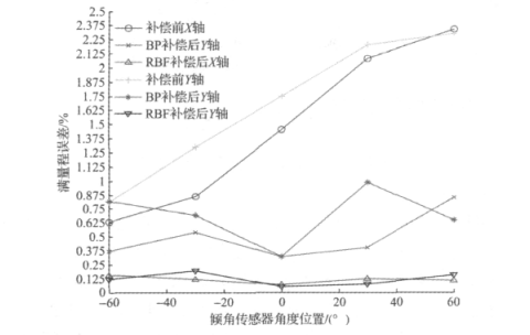
The target difference of BP neural network training is 1e^(-4), and that of RBF neural network training is 1e^(-6). However, the training time of RBF neural network is only about 1/2 of that of BP network, which shows that RBF convergence speed is relatively ideal. At the same time, the zero point temperature drift and sensitivity temperature drift before and after compensation are shown in following table. BP network and RBF network reduce the zero point and sensitivity temperature drift by 1 and 2 orders of magnitude respectively. The full scale error diagram of the inclination sensor under the action of -20~70℃ is shown in the figure below.

the zero point temperature drift and sensitivity temperature drift before and after compensation

full scale error diagram of the inclination sensor under the action of -20~70℃

The maximum full scale error before compensation is about 2.34%, after BP neural network modeling compensation is about 0.85%, and after RBF modeling compensation is reduced to 0.158%. The simulation results show that the output error of the tilt sensor decreases after temperature compensation, and the output error decreases from 2.8° before compensation to 0.23° after conversion to angle degree. The modeling effect of RBF neural network is much better than that of BP network model, and it is very close to the actual expected value. Therefore, for the inclination sensor in this paper, RBF neural network modeling compensation can obtain better compensation effect.

Concluding discussion
We use RBF neural network compared with BP network to realize the research of temperature compensation of inclination sensor. The experimental results show that the RBF neural network modeling compensation achieves good compensation results in this system: for zero temperature drift, the X-axis decreases from 1.61×10^(-4) before compensation to 7.41×10^(-6), and the Y-axis decreases from 1.94×10^(-4) before compensation to 5.56×10^(-4). For sensitivity temperature drift, the X-axis decreased from 2.05×10^(-4) before compensation to 5.56×10^(-6), and the Y-axis decreased from 1.84×10^(-4) before compensation to 4.63×10^(-6). The RBF neural network is used to compensate the temperature of the inclinometer sensor, which reduces the influence of temperature on the sensor, overcomes the disadvantage that BP network is easy to fall into local optimal, improves the stability and measurement accuracy of the system, and lays a foundation for the application of the inclination sensor in various industries.

For example, Ericco’s ER-TS-12200-Modbus and ER-TS-32600-Modbus, both of which are dual-axis monitoring, we can completely carry out temperature compensation through RBF neural network modeling, and after compensation, the zero temperature drift and sensitivity temperature drift value of X axis and Y axis will be greatly reduced. In this way, we can reduce or even eliminate the adverse effects of temperature on the inclinometer sensor. 

RTK signal is easily blocked? IMU makes RTK have unlimited possibilities

When you use an RTK surveying instrument to measure in some places with obstructions or requiring a large tilt, do you always encounter weak...