Showing posts with label gyro sensor. Show all posts

Monday, July 8, 2024

How does Tactical Fiber Optic Gyroscope Work?


Fiber optic gyroscope industry market

With its unique advantages, fiber optic gyroscope has a broad development prospect in the field of precision physical quantity measurement. Therefore, exploring the influence of optical devices and physical environment on the performance of fiber optic gyros and suppressing the relative intensity noise have become the key technologies to realize the high precision fiber optic gyro. With the deepening of research, the integrated fiber gyroscope with high precision and miniaturization will be greatly developed and applied.

Fiber optic gyroscope is one of the mainstream devices in the field of inertia technology at present. With the improvement of technical level, the application scale of fiber optic gyro will continue to expand. As the core component of fiber optic gyros, the market demand will also grow. At present, China's high-end optical fiber ring still needs to be imported, and under the general trend of domestic substitution, the core competitiveness of China's optical fiber ring enterprises and independent research and development capabilities still need to be further enhanced.

At present, the optical fiber ring is mainly used in the military field, but with the expansion of the application of optical fiber gyroscope to the civilian field, the application proportion of optical fiber ring in the civilian field will be further improved.

According to the "2022-2027 China Fiber Optic Gyroscope industry Market Survey and Investment Advice Analysis Report" :

The fiber optic gyroscope is a sensitive element based on the optical fiber coil, and the light emitted by the laser diode propagates along the optical fiber in two directions. The difference of light propagation path determines the angular displacement of the sensitive element. Modern fiber optic gyro is an instrument that can accurately determine the orientation of moving objects. It is an inertial navigation instrument widely used in modern aviation, navigation, aerospace and national defense industries. Its development is of great strategic significance to a country's industry, national defense and other high-tech development.
Fiber optic gyro is a new all-solid-state fiber optic sensor based on Sagnac effect. Fiber optic gyro can be divided into interferometric fiber optic gyros (I-FOG), resonant fiber optic gyro (R-FOG) and stimulated Brillouin scattering fiber optic gyro (B-FOG) according to its working mode. According to its accuracy, fiber optic gyro can be divided into: low-end tactical level, high-end tactical level, navigation level and precision level. Fiber optic gyroscopes can be divided into military and civilian according to their openness. At present, most fiber optic gyros are used in military aspects: fighter and missile attitude, tank navigation, submarine heading measurement, infantry fighting vehicles and other fields. Civil use is mainly automobile and aircraft navigation, bridge surveying, oil drilling and other fields.
Depending on the accuracy of the fiber optic gyroscope, its applications range from strategic weapons and equipment to commercial grade civilian fields. Medium and high-precision fiber optic gyroscopes are mainly used in high-end weapons and equipment fields such as aerospace, while low-cost, low-precision fiber optic gyroscopes are mainly used in oil exploration, agricultural aircraft attitude control, robots and many other civilian fields with low precision requirements. With the development of advanced microelectronics and optoelectronics technologies, such as photoelectric integration and the development of special fiber optics for fiber optic gyros, the miniaturization and low-cost of fiber optic gyros have been accelerated.

Summary

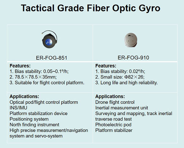
Ericco's fiber optic gyro is mainly a medium precision tactical fiber optic gyro, compared with other manufacturers, low cost, long service life, the price is very dominant, and the application field is also very wide, including two very hot selling ER-FOG-851ER-FOG-910, you can click the details page for more technical data,

Tactical Grade Fiber Optic Gyro Comparison

If you have any purchase needs, feel free to send the inquiry, or contact us directly: Phone: +86-13992884879
Email: info@ericcointernational.com.

Wednesday, May 15, 2024

Fiber Optic Gyroscopes for Inertial Navigation


1. What is inertial navigation

To understand what inertial navigation is, we first need to break the phrase into two parts, that is, navigation + inertia.
Navigation, in simple terms, solves the problem of getting from one place to another, indicating the direction, typically the compass.
Inertia, originally derived from Newtonian mechanics, refers to the property of an object that maintains its state of motion. It has the function of recording the motion state information of the object.
A simple example is used to illustrate inertial navigation. A child and a friend play a game at the entrance of a room covered with tiles, and walk on the tiles to the other side according to certain rules. One forward, three left, five front, two right... Each of his steps is the length of a floor tile, and people outside the room can get his complete motion trajectory by drawing the corresponding length and route on the paper. He doesn't need to see the room to know the child's position, speed, etc.
The basic principle of inertial navigation and some other types of navigation is pretty much like this: know your initial position, initial orientation (attitude), the direction and direction of movement at each moment, and push forward a little bit. Add these together (corresponding to the mathematical integration operation), and you can just get your orientation, position and other information.
So how to get the current orientation (attitude) and position information of the moving object? You need to use a lot of sensors, in inertial navigation is the use of inertial instruments: accelerometer + gyroscope.
Inertial navigation uses gyroscope and accelerometer to measure the angular velocity and acceleration of the carrier in the inertial reference frame, and integrates and calculates the time to obtain the velocity and relative position, and transforms it into the navigation coordinate system, so that the carrier's current position can be obtained by combining the initial position information.
Inertial navigation is an internal closed loop navigation system, and there is no external data input to correct the error during the carrier movement. Therefore, a single inertial navigation system can only be used for short periods of navigation. For the system running for a long time, it is necessary to periodically correct the internal accumulated error by means of satellite navigation.

2. Gyroscopes in inertial navigation

Inertial navigation technology is widely used in aerospace, navigation satellite, UAV and other fields because of its high concealment and complete autonomous ability to obtain motion information. Especially in the fields of micro-drones and autonomous driving, inertial navigation technology can provide accurate direction and speed information, and can play an irreplaceable role in complex conditions or when other external auxiliary navigation signals fail to play the advantages of autonomous navigation in the environment to achieve reliable attitude and position measurement. As an important component in inertial navigation system, fiber optic gyro plays a decisive role in its navigation ability. At present, there are mainly fiber optic gyroscopes and MEMS gyroscopes on the market. Although the precision of the fiber optic gyroscope is high, its entire system is composed of couplers,
Modulator, optical fiber ring and other discrete components, resulting in large volume, high cost, in the micro UAV, unmanned and other fields can not meet the requirements for its miniaturization and low cost, the application is greatly limited. Although MEMS gyro can achieve miniaturization, its accuracy is low. In addition, it has moving parts, poor resistance to shock and vibration, and is difficult to apply in harsh environments.


3 Summary

Ericco's fiber optic gyroscope ER-FOG-851 is specially designed according to the concept of traditional fiber optic gyroscopes, with a small size of 78.5*78.5*35mm; Light weight, less than or equal to 300g; Low power consumption, less than or equal to 4W; Start fast, start time is only 5s; This fiber optic gyroscope easy to operate and easy to use, and is widely used in INS, IMU, positioning system, north finding system, platform stability and other fields.
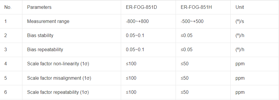
The accuracy of our ER-FOG-851 is between 0.05 and 0.1, and the 851 is divided into ER-FOG-851D and ER-FOG-851H. The biggest difference between these two fiber optic gyroscope is that the measurement range is different, of course, the accuracy is different, and the measurement range of ER-FOG-851D is wider. The application range is naturally wider than the ER-FOG-851H. Our fiber optic gyroscope can be used in inertial navigation, you can make a detailed choice according to the accuracy value and measurement range, you are welcome to consult us at any time and get more technical data.


Range And Zero Bias Of Fiber Optic Gyroscope Er Fog 851

Friday, May 10, 2024

Features of Fiber Optic Gyroscope


1.Characteristics of fiber optic gyro

Compared with electromechanical gyro or laser gyro, fiber optic gyro has the following characteristics:

(1) fewer parts, the instrument is firm and stable, and has a strong ability to resist impact and accelerate movement;
(2) The wound fiber is longer, so that the detection sensitivity and resolution are several orders of magnitude higher than that of the laser gyroscope;
(3) No mechanical transmission parts, no wear problems, so it has a long service life;
(4) Easy to use integrated optical path technology, signal stability, and can be directly digital output, and connected with the computer interface;
(5) By changing the length of the fiber or the number of times the light circulates in the coil, different accuracy can be achieved and a wide dynamic range can be achieved;
(6) The propagation time of the coherent beam is short, so in principle it can be started instantaneously without preheating;
(7) can be used with ring laser gyro to form sensors of various inertial navigation systems, especially sensors of strapdown inertial navigation systems;
(8) Simple structure, low price, small size, light weight.

2.Principle of fiber optic gyroscope

Fiber optic gyro is a fiber optic angular velocity sensor, which is the most promising one among all kinds of fiber optic sensors. Like ring laser gyro, fiber optic gyro has the advantages of no mechanical moving parts, no preheating time, insensitive acceleration, wide dynamic range, digital output and small size. In addition, fiber optic gyro also overcomes the fatal shortcomings of ring laser gyro such as high cost and blocking phenomenon. Therefore, fiber optic gyro has been paid attention to by many countries. Low precision civilian fiber optic gyro has been produced in small batch in Western Europe, it is estimated that in 1994, the sales of fiber optic gyro in the United States gyro market reached 49%, and the cable gyro fell to the second place (accounting for 35% of sales).

The working principle of fiber optic gyroscopes is based on the Sagnac effect. Sagnac effect is a general correlation effect of light propagated in a closed loop optical path rotating relative to inertial space, that is, two beams of light with equal characteristics emitted from the same light source in the same closed optical path propagate in opposite directions, and finally converge to the same detection point.

3.Application of fiber optic gyro

What if a car with a satellite navigation system is driving and suddenly can't receive GPS navigation signals? With the addition of a fiber optic gyroscope, it can form integrated navigation with GDS to achieve automatic driving.

Fiber optic gyro technology is based on mechanical gyro, MEMS gyro, laser gyro upgrade and development, with self-correcting, high sensitivity, long life, low temperature and high temperature resistance, no electromagnetic interference and many other advantages, is the best comprehensive performance of inertial sensors. Due to high cost, it is mainly used in military industry, aerospace and other fields.

Fiber optic gyro technology can be widely used in automotive navigation, high-speed rail track detection, Internet of Things components module, smart grid transmission, consumer electronics and many other fields, experts predict that the potential market size of domestic fiber optic gyro reached 100 billion, the next 5-10 years, most of China's traditional gyro market will be replaced by fiber optic gyro.

4.Summary

Ericco's fiber optic gyro is also a leading level in the world, ER-FOG-851 (≤0.05 ~ 0.1º/h), ER-FOG-910(0.02º/h) are a good choice, because they are medium precision, widely used, if you want to get more technical parameters, please feel free to contact us.

Tuesday, March 5, 2024

Soft Magnetic Error Compensation Method of Electronic Compass


1. Analysis of soft magnetic error of electronic compass

There is another ferromagnetic substance in the working environment of the electronic compass sensor, which, unlike hard ferromagnetic materials, is easily magnetized in a weak magnetic field. When the external magnetic field changes, its induced magnetism will also undergo a related change. The size and direction of the induced magnetic field will also change with the attitude and position of the carrier.
Because of its special properties, this material is called soft iron material. This soft iron material magnetizes itself due to the size of the external magnetic field it receives to produce a magnetic field that resists changes in magnetic flux, which can vary over a wide range. If the magnetic field in the space where the electronic compass sensor is located is known, the magnetic field actually measured by the electronic compass sensor is equal to the superposition of the geomagnetic field and the magnetic field generated by the soft iron interference. The soft iron error is equivalent to a time-varying error superimposed on the output of the electronic compass sensor. Because of the different properties of soft magnetic interference error and hard magnetic interference error, the least square method is no longer applicable when compensating soft magnetic interference error. Soft magnetic interference will lead to the deviation of the measurement Angle of the electronic compass. In an ideal environment, the Angle rotated by the measurement of the electronic compass is controllable, but the existence of soft magnetic interference error will lead to the deviation and uncontrollable Angle of the measurement process of the electronic compass. In the application of navigation system, a small Angle difference will lead to a large route error. The modern electronic compass has strong anti-interference and can suppress most of the Angle deviation, but the compensation of soft magnetic error is still worth studying and discussing.

2. Soft magnetic interference error compensation method
In the actual use of electronic compass, the noise errors caused by soft magnetic interference are mostly random noise errors. At present, there are many algorithms that can be used to compensate random noise and most of them are relatively mature, but considering the characteristics of electronic compass requiring real-time and rapid processing of large amounts of data. Three very mature random noise compensation algorithms, namely Kalman filter, improved Sage adaptive Kalman filter and particle filter, are selected as soft magnetic interference compensation algorithms. These three algorithms are easy to implement and can handle dense data.

2.1 Kalman filter
Kalman filtering algorithm can estimate the linear system with Gaussian white noise, which is the most widely used filtering method at present, and has been well applied in the fields of communication, navigation, guidance and control. The basic idea is that the minimum mean square error criterion is the best estimation criterion, and the future state quantity of the system is estimated by recursion theory, so that the estimated value is as close as possible to the real value.

2.2 Adaptive Kalman filtering
Traditional Kalman filter requires that the mean of dynamic noise and observed noise of the system be zero, and the statistical characteristics are known white noise, but these conditions may not be satisfied in practice, so there are modeling errors. Due to the limitation of objective conditions such as computing tools, the filtering algorithm is easy to produce error accumulation when running on the computer. This results in the loss of positivity or symmetry of error covariance matrix and the instability of numerical calculation.

2.3 Particle filter algorithm
The particle filter algorithm originated from the research of Poor Man's Monte Carlo problem in the 1950s, but the first applied particle filter algorithm was proposed by Gordon et al in 1993. The particle filter is based on the Monte Carlo method, which uses sets of particles to represent probabilities and can be used for any form of state-space model. Particle filter can accurately express the posterior probability distribution based on the observed and controlled quantities, and is a sequential important sampling method. Bayesian inference and importance sampling are the basis of understanding particle filtering.

3.Allan variance simulation experiment
The Allan analysis of variance is used to simulate the original data of random sequence, the data compensated by Kalman filter algorithm, the data compensated by particle filter algorithm, and the four groups of data compensated by adaptive Kalman filter algorithm. Verify the feasibility of Allan variance analysis algorithm. The Allan standard deviation curve of each data is drawn according to the analysis results. The Allan standard deviation curves of the four groups of data are shown in FIG. 14-17 respectively.

Fig 14 Allen variance curve of raw data

The compensated Allen variance curve

4. Summary
From FIG. 14 to FIG. 17, it can be seen that the Allan variance program of the paper can effectively analyze the experimental data.
Several sets of experimental data show that the program is effective.

Different algorithm compensation results

After analyzing the data before and after compensation, it can be seen that the quantization noise and zero bias instability noise of the data after compensation by Kalman filter algorithm are reduced by 64% and 66.4% respectively. The quantization noise and zero bias instability noise of the compensated particle filter data are reduced by 70% and 72.1% respectively. The quantization noise and zero bias instability noise of the data compensated by adaptive Kalman filter are reduced by 91.5% and 75.7% respectively. All the algorithms we mentioned can have a better compensation effect for the original data noise.
It can be seen from the compensation effect that compared with traditional Kalman filter and particle filter, adaptive Kalman filter can better remove the noise in the original data, and filter the noise of ER-EC-385ER-EC-365B and other types of electronic compass. The random data in the simulation experiment is based on the simulation of the noise caused by soft magnetic interference. The simulation results show that the filtering algorithm can compensate the noise of soft magnetic interference. 

Tuesday, November 7, 2023

Application of gyroscope in directional measurement of long-distance subway tunnel


Orientation control is particularly important in the directional measurement of long-distance subway tunnels, and is a necessary condition to ensure the smooth penetration of the tunnel. The conventional directional measurement method is to use contact measurement or wire measurement to transmit the orientation. Inertial orientation has incomparable advantages that conventional measurement methods. This article proposes The north-seeker orientation was applied in the directional measurement of long-distance subway tunnels, which verified the effectiveness of the north-seeker in the directional measurement of long-distance cross-sea tunnels.

In order to improve the penetration accuracy of subway tunnels, many rail transit (subway) systems have recently introduced the highest. Accurate, gyroscopic north finder used for directional measurement in subway tunnels.In the construction measurement of subway tunnels, the measurement accuracy of the underground conductor control network is often related to the penetration of the tunnel.Error, high-precision penetration is very important for track engineering construction.

The gyro north finder is a measuring device that finds the true north value of a certain location. It is combined with known ground control

points, which can provide precise direction values for underground conductor control points. Underground conductors are generally connected through shafts

System survey introduces the coordinates of ground control points into the underground. Due to the limitation of shaft size, ultra-short

While controlling the direction of tunnel excavation, the one-way excavation length is too long in some sections.

These conditions have laid hidden dangers for the smooth penetration of the subway tunnel. Therefore, small-sized north seekers are widely favored: for example, ER-MNS-06, with a size of only 44.84×38.88×21.39mm, can be applied to most excavation fields.

The ER-FNS-02 gyro north finder introduced this time is 1 to 3 times more accurate than traditional measurement, with an accuracy of 0.02° to 0.1°. In vertical shafts, the accuracy is more reliable and has greater improvement.

Technicians from the rail transit third-party measurement project tested the orientation accuracy of the gyro north finder when orienting the tunnel. Through on-site testing, it was found that its orientation accuracy was much higher than the accuracy requirements for the tunnel's lateral penetration error required by the specification. This new technology will be used in more rail transit construction.

If you are interested in this north finder, you can leave me a message or send a quote and I will send you the price and technical description.

Email: info@ericcointernational.com

WeChat: 13992884879

WhatsApp: 13630231561


Sunday, October 22, 2023

The Difference between Tilt Sensor and Gyro Sensor


The tilt sensor senses the angle of inclination deviation, only data feedback but no command feedback.

The gyroscope measures the angular velocity, senses the action variable, and then controls the steering gear to carry out the repair action command.

The tilt sensor uses Newton’s second law as its working principle. According to the law, we know that when the inclination sensor is stationary, because the side of the object and the vertical direction are affected by other forces, only the action of gravity, that is to say, it acts on the all it has on it is the acceleration of gravity. Therefore, the resulting angle between the vertical axis of gravity and the sensitive axis of the acceleration sensor is what we call the inclination angle, which is the angle we seek.

Tilt sensors are divided into three different working principles and are divided into three types. The first type of inclination sensor is the solid pendulum type, the second type of inclination sensor is called the liquid pendulum type, and the last type of inclination sensor is the gas pendulum type. The working principles of these three different types of inclination sensors will be different. Because of their different working principles, they will have different advantages and disadvantages.

No matter which type of tilt sensor it is, it will be substantially different from a gyroscope. Like inclination sensors, no matter which type it is, it measures the inclination angle at rest. Compared with the inclination sensor, the gyroscope measures the inclination in motion, and the measurement result of the inclination in static is not accurate. So when we measure the inclination in our daily life, whether to choose the inclination sensor or the gyroscope, we can choose according to this essential difference. If the inclination is measured at rest, then the inclination sensor must be selected, and the inclination in motion is measured, and of course the gyroscope is selected. The specific differences are summarized as follows:

1.Different definitions

The gyroscope is an angular motion detection device that uses the momentum moment-sensitive shell of a high-speed revolving body relative to the inertial space around one or two axes that are orthogonal to the axis of rotation. There are many varieties of gyroscopes, which can be divided into sensing gyroscopes and indicating gyroscopes according to their usesThe ER-MG2-022 is a single-axis MEMS angular rate sensor (gyroscope) capable of measuring angular velocity up to a maximum of ±100°/s with digital output compliant to SPI slave mode 3 protocol.  Angular rate data is presented as a 24-bit word, intended for north seeking applications.  An advanced, differential sensor design rejects the influence of linear acceleration, enabling the ER-MG2-022 to operate in exceedingly harsh environments where shock and vibration are present.

The sensor gyroscope is used in the automatic control system of the flying body movement, as a horizontal, vertical, pitch, heading and angular velocity sensor. The indicating gyroscope is mainly used for the indication of the flying condition, and is used as a driving and piloting surface.

2.Different functions

The tilt sensor measures the inclination of all stops. Compared with the inclination sensor, the gyroscope measures the inclination angle during the movement, and the measurement result of the inclination angle in the static state is inaccurate. The gyroscope is not a measuring device, but an auxiliary device. Just like the tank barrel, in order to allow the tank to shoot accurately during the trek, a gyroscope is installed to automatically control the viewpoint of the barrel.

3.Different applications

The tilt sensor is often used for the level measurement of the system. From the working principle, it can be divided into three types of inclination sensors: “solid pendulum”, “liquid pendulum” and “gas pendulum”. The inclination sensor can also be used to measure the inclination relative to the horizontal plane. The amount of change.

The gyroscope sensor was originally used on the helicopter model, and it has been widely used in mobile portable devices such as mobile phones. Not only that, the modern gyroscope is an instrument that can accurately determine the orientation of moving objects, so the gyroscope Sensors are essential controls in modern aviation, marine, aerospace and defense industrial applications.

Choose a suitable IMU to make your drone flight more stable and safe

         As one of the core components of drones, IMU plays an irreplaceable role. Its high precision, fast response and freedom from extern...