Showing posts with label tilt meter. Show all posts

Thursday, April 25, 2024

Measurement of Moving Airfoil Deflection based on Wireless Tilt Sensor

 Based on the underlying measurement principle of the tilt sensor, considering the sensor system error, operation and installation error, and referring to the existing spatial Angle error analysis model, we improve the spatial Angle biaxis measurement error model suitable for the situation of moving airfoil deflection around the horizontal axis, and improve the calibration method according to the working condition. By using wireless transmission as a communication method, a complete set of moving wing deflection test system is built, which can display the Angle information of the moving wing in real time by visual means such as data, curves and three-dimensional models. The deflection Angle measurement accuracy is less than 0.05°, and the acquisition frequency is higher than 10 Hz, which can meet the actual measurement requirements.

Modern aircraft manufacturing mainly adopts modular assembly technology, the whole aircraft components in the assembly line to complete modular manufacturing and equipment installation test, and finally complete the docking of large parts on the final assembly pulsating production line to form the whole machine. For large aircraft, there are many types and quantities of movable airfoil, high profile accuracy requirements, many control and coordination links involved, large manufacturing and debugging workload, and complex installation and debugging processes.

The detection of deflection Angle is an important part of modular wing assembly test. There are many types and complex structure of the rudder surface of a certain key model, and the tilt sensor equipment installation of the traditional method of wing deflection Angle detection is cumbersome, the types of mechanical fixtures required are large, and the operation of workers is time-consuming and laborious. With the growing demand for various types of high-performance aircraft, the manufacturing tasks of aircraft manufacturers are increasing, and the production line needs an accurate, fast and real-time movable wing automatic inspection operating system that can reflect the production process in real time to improve the production line efficiency and ultimately increase the aircraft output.
At present, the commonly used methods to detect the deflection Angle of the active airfoil space include inertial measurement, laser tracker detection, visual detection, coordinate detection, multi-theodolite detection, linear displacement or angular displacement sensor indirect detection, mechanical protractor, etc. The methods are various, but all have certain shortcomings. Therefore, many studies have combined the above methods to improve the accuracy and applicability of measurement. The inertial measurement method based on tilt sensor is relatively portable, the measurement accuracy and efficiency can meet the actual demand, so we finally choose this method to test the deflection of moving airfoil.

System design and implementation

(1) A biaxial measurement error model is proposed for the scenario of the active airfoil deflecting around the horizontal axis. Considering the actual working conditions of the active airfoil deflecting, a new error variable is introduced to improve the calibration algorithm, so that the tilt sensor calibration algorithm can adapt to the special working conditions of the unparallel mounting surface. The calibrated sensor Angle output accuracy is improved, and the error is within the allowable range, which can meet the high precision testing requirements of the wing moving surface Angle.
(2) Complete the design and implementation of a large aircraft wing active wing deflection test system based on wireless communication protocol, and the field verification that it can achieve the mission objectives. Compared with the previous system, the hardware installation of the system does not need to connect wired communication cables, and the operation is simple. The calibration work can be automatically completed through software control, and the accuracy and real-time performance of data transmission under the wireless network can also be guaranteed, which can significantly improve the work efficiency of field active wing deflection test.
(3) Only installation errors were considered in the analysis of the measurement model of spatial Angle. In fact, there is coupling between all kinds of errors. In the subsequent research, we can try to identify all kinds of errors of the system as a whole to improve the measurement accuracy of the calibration model.

Summary

Ericco's two very popular wireless tilt sensors, ER-TS-12200-Modbus, accuracy can reach 0.001°, resolution 0.0005°, ER-TS-32600-Modbus accuracy moderate 0.01°, resolution 0.002°, you can choose according to your own needs, If you are interested in our wireless tilt sensors, please feel free to contact us.

Sunday, January 14, 2024

Application of Tilt Sensor in the Settlement of Railway Track Subgrade


The tilt sensor can be well applied in the remote automatic monitoring system of subgrade settlement.

In order to ensure the high-speed and healthy development of railway, the remote automatic monitoring system of subgrade settlement based on laser measurement, advanced sensing and wireless network technology is developed. The monitoring system includes four sub-systems: automatic measurement of surface settlement by laser, simultaneous automatic measurement of subgrade stratified settlement and lateral displacement, automatic measurement of subgrade lateral profile settlement, data acquisition and wireless transmission. Automatic measurement of surface settlement is achieved by laser measurement and automatic calibration technology: simultaneous automatic measurement of subgrade stratified settlement and lateral displacement is achieved by Hall sensor, laser ranging and dip angle transmission sensor realization: The automatic measurement of subgrade transverse profile settlement is achieved by the tilt sensor driven by the main and slave motors. The monitoring system has been verified by laboratory and designed by engineering, and has been tested in a station of high-speed railway.

The ER-TS-12200-Modbus tilt sensor can be well applied in the control system, so as to realize real-time monitoring of the overall settlement of the subgrade, local settlement and the settlement of different layers in the section, and transmit the output signal of the tilt sensor to the computer through wireless transmission or various wired networks. Then the received data is processed, analyzed and stored by computer software.

If you want to learn more about MEMS tilt sensors or buy tilt sensors

Please contact me in the following ways:

Email: info@ericcointernational.com

Whatsapp: 13992884879


Thursday, January 11, 2024

Tilt sensor, Tilt Switch&Other Common Problems in Installation and Use Process


Question 1: What is the resolution of a tilt sensor?

A: It refers to the smallest change to be measured that can be detected and distinguished by the tilt sensor within the measurement range.

Question 2: What is precision?

A: Accuracy refers to the actual angle and tilt sensor measurement angle multiple times (>24 times) root mean square value error of the measurement.

Question 3: How can the sensor be installed to ensure its best accuracy?

A: During installation, the sensor mounting surface should be kept parallel to the target of the measured surface, and the influence of dynamic and acceleration on the sensor should be reduced. The product can be installed horizontally or vertically, and the vertical installation is suitable for single-axis tilt sensor, which is suitable for measuring range < The 60-degree product is installed horizontally, and the front of the sensor is marked with X and Y direction indication stickers, which can be referred to when installing.

Question 4: What does offset mean in analog output sensors?

A: Zero bias voltage, if you customize the 0~5V output, then the zero position voltage output 2.5V.

Question 5: The larger the measurement range of the inclination sensor, does it determine the better and more expensive the product?

A: Can not be understood in this way, relatively speaking, the size of the range and the accuracy will be inversely proportional, the smaller the range, the higher the accuracy, the price is not directly related to the range.

Question 6: How can the visual value be less than the actual measured value (especially for the tilt alarm of the platform monitored by the tilt switch, the old-fashioned alarm)?

A: There may be an installation angle when the tilt switch is installed, and at this time, the tilt switch has an initial angle, so that the actual application will appear larger than the visual angle, and an alarm will occur.

Question 7How can the visual angle of an electronic compass be greater than the measured angle?

Answer: Because the two axes of the inclination measurement are the most sensitive, when the inclination direction is not aligned with the measurement axis, the actual value will be greater than the measured value, which can also be understood as a projection.

Question 8: Which direction does the single-axis and dual-axis measurement of the tilt sensor refer to?

A: The double axis can measure the rollover (X direction) and pitch angle (Y direction), while the single axis can only measure the rollover angle or pitch angle when selecting the horizontal installation. If the single axis can only measure the rollover angle when selecting the vertical installation, the pitch angle is not optional.

Question 9: Do your products work well in harsh industrial environments?

A: At present, our products are used in various industrial control fields, including underground non-underground mining machinery, underwater machinery, Antarctic survey, oil drilling, etc., and the work is very stable.

Question 10: How to understand course accuracy?

A: The course accuracy refers to the root-mean-square error, not a random error, and to compensate for the influence of the surrounding static magnetic field, and the magnetic inclination should not be greater than 75 degrees of the value.

Question 11: In actual use, the electronic compass can not reach the nominal accuracy, especially in the measurement of the presence of pitch angle and roll angle.

A: Generally, the environment at the time of calibration is different from that at the time of use, so the calibration failure cannot guarantee the established indicators. If there is no tilt or roll in the rotation of the electronic compass during calibration, but there is a tilt and roll phenomenon in actual use, so this calibration is not effect.

Question 12: Axis alignment problem during installation of electronic compass?

A: The north point on the mounting surface of the electronic compass can be at a certain angle with the axis of the mounted body, which can be solidified into the memory body in the device through the setting software of the electronic compass for normal use to correct the output value.

Question 13: Electronic compass installation precautions?

A :1. In order to avoid strong magnetic interference, please be more than 0.5 meters away from the magnetic field source;

  1. If there is magnetic field interference of other supporting products around the installation, it is recommended to calibrate the device before using it. For details about the calibration method, see the calibration instructions in the product manual or consult technical support.

In Summary:

Question 5 we mentioned above: Does the larger the measurement range of the tilt sensor determine the better and more expensive the product?

A: Can not be understood in this way, relatively speaking, the size of the range and the accuracy will be inversely proportional, the smaller the range, the higher the accuracy, the price is not directly related to the range.

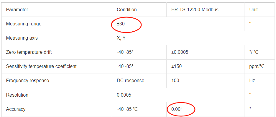
Let’s take these two wireless tilt sensors as an example, the measuring range of ER-TS-12200-Modbus is ±30°, the measuring range is very small, but its accuracy reaches 0.001°. Small range but high precision.

ER-TS-12200-MODBUS tilt sensor's resolution and accuracy

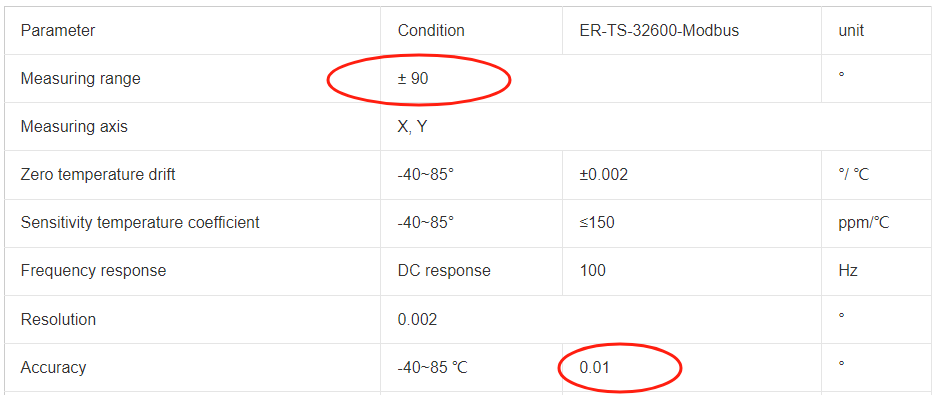
We use this product ER-TS-32600-Modbus for comparison. Its range is ±90°, which is larger than the above product, but its accuracy is only 0.01°. It can be seen that the range size and accuracy are indeed inversely proportional.

ER-TS-32600-MODBUS tilt sensor's resolution and accuracy

Customers in the use of the process may encounter some common problems, these problems are often consulted by customers in the past, in order to avoid causing unnecessary trouble to customers, Ericco listed here with the majority of customers and peers to share our experience. 

Wednesday, January 3, 2024

Resolution and Accuracy of Tilt Sensors


Accuracy and resolution of tilt sensors

Resolution refers to the sensor in the measurement range can detect and resolve the smallest change in the measured value. The accuracy refers to the error between the angle measured by the sensor and the real angle.

The relationship between precision and resolution with examples 

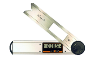
Take the familiar vernier calipers. We often say that the accuracy of the vernier caliper is 0.1mm, in fact, this statement is not correct, it should be said that the resolution of the vernier caliper is 0.1mm. That is, when the change in length is 0.1mm, Can our eyes see it, tell it apart. The accuracy of the vernier caliper, because the accuracy represents the difference between the measured value and the true value, the accuracy is related to many factors. For example, temperature causes thermal expansion and contraction, when we see a change of 0.1mm, the real may be 0.09mm, such as the caliper bending, or the caliper engraving line is not particularly uniform, will lead to poor accuracy, but the resolution is still 0.1mm. To improve the accuracy of the measurement, we must first improve the resolution of the measurement, if the resolution can not be distinguished, then the accuracy from where to start. Resolution is the limit of accuracy, improve the resolution at the same time to eliminate the impact of other factors on the accuracy, in order to effectively improve the final accuracy.

The angle sensor based on acceleration principle is illustrated in detail. It is the measurement of gravitational acceleration on the sensitive axis of the acceleration sensor into angle data, that is, the angle value and the acceleration value into a sine relationship.

The resolution of tilt sensors are also often referred to as sensitivity. It is mainly caused by the noise of the sensor. The noise equivalent angular change is called the angular resolution. Because the size of the noise is related to the frequency response, the higher the frequency response, the greater the noise. The resolution of the sensor can be improved effectively by taking effective measures to suppress the noise. After the resolution is improved, there is a chance to compensate for the adverse impact of other factors on the accuracy.

Resolution accuracy of vernier calipers

Other factors affecting the accuracy of tilt sensors

Of course, there are many factors that affect the accuracy of tilt sensors, in addition to the most important resolution, but also include:

Zero bias–depending on the characteristics of the core sensitive device itself, it means that the sensor in the absence of angle input (such as absolute horizontal plane), the sensor measurement output is not zero, the actual output angle value is zero bias.

Nonlinearity— can be corrected later, depending on the number of correction points. The more correction points, the better the nonlinearity.

Horizontal axis error— refers to the error caused by coupling to the output signal of the sensor when the sensor applies a certain acceleration perpendicular to its sensitive axis or tilts at a certain angle.

Input shaft non-alignment – refers to the installation deviation of the sensor in the actual installation process, which actually includes the input shaft non-alignment and vertical shaft non-alignment errors.

Sum up

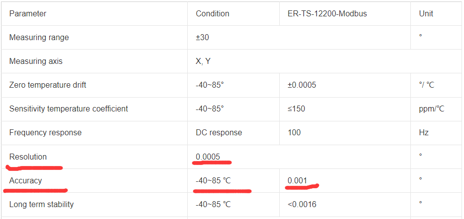
We use specific tilt sensors products to look at the relationship between resolution and accuracy, for example, our ER-TS-12200-Modbus, from the main parameters can be seen, its resolution is 0.0005°, that is, within the measurement range of ±30° can detect and distinguish the smallest change value measured is 0.0005°, the resolution is quite high. The comprehensive accuracy within the full temperature of -40~85° can reach 0.001°, because its resolution has been improved a lot, so its accuracy is naturally improved. 

Resolution and accuracy of High Precision Wireless Transmission Tilt Sensor

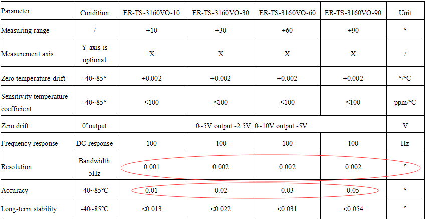
In the following figure, the main parameters of ER-TS-3160VO Low cost Voltage Type Single Axis Tilt Sensor, in different measurement ranges, its resolution is not the same, at ±10° its resolution can reach 0.001°, the accuracy is 0.01°. By comparing the parameters of these two products, we can see a relationship between resolution and accuracy. The resolution is low, the accuracy is relatively low, if the resolution is improved, the accuracy will be improved accordingly.

Resolution and accuracy of Low Cost Voltage Type Single Axis Tilt Sensor

Monday, January 1, 2024

The Advantages and Disadvantages of the Transmission Mode of Tilt Sensor


In today’s industrial and commercial environment, tilt sensors are increasingly used to measure and monitor the tilt angle of equipment or structures. Depending on the data transmission method, tilt meters can be divided into wired and wireless types. In this article, we’ll delve into both types of tilt sensors, including the pros and cons, and how to choose the best solution for your specific needs. 

1. Advantages&disadvantages of wired tilt sensor

Wired inclination sensor built-in high performance MCU built-in algorithm, through a high oversampling rate, improve the high frequency characteristics of the data, through the data filtering algorithm to remove unreasonable accidental error data, Kalman filter algorithm for higher precision data processing, suitable for monitoring the structure deformation monitoring field with high monitoring frequency requirements. Wired tilt meters usually use RS485 bus or other similar bus protocols to transmit inclination signals. RS485 is a serial communication protocol widely used in the field of industrial automation, which has the advantages of noise suppression and high signal quality. ER-TS-3160VO is a linear inclination sensor with an accuracy of 0.01°, its cable standard length is 1.5m, and it can output RS232 at the same time, RS485 can be customized, the measurement range can reach 0~±180°, and the impact vibration resistance is strong.

The main advantage of the wired tilt meters is that the signal stability is high, and the signal quality is not easy to be disturbed because of the wired transmission mode. In addition, wired sensors have a long service life, lower maintenance costs, and a lower failure rate. However, this sensor also has some disadvantages, such as the need to lay cables, high requirements for the field environment, may exist in some application scenarios wiring difficulties. 

2. Advantages&disadvantages of wireless tilt sensor

Wireless tilt meters have become more and more popular in recent years, and common wireless inclination sensors include NB-IoT wireless inclination sensors and LORO wireless inclination sensors. These sensors transmit tilt signals via wireless communication technology without cable connections, making them highly flexible.

The main advantages of wireless tilt sensors are their flexibility and convenience. Since no wiring is required, the sensor can be easily installed anywhere it is needed, without considering the laying of cables. In addition, wireless sensors also have the advantages of high mobility, easy expansion and maintenance. However, wireless sensors also have some disadvantages, such as signal quality may be affected by radio interference, and signal stability and reliability may not be as good as wired sensors. ER-TS-12200-Modbus is a high-precision tilt sensor using Bluetooth and ZigBee wireless transmission technology of the internet of things, eliminating the complicated wiring and noise interference caused by long cable transmission, using lithium battery power supply, good long-term stability, zero drift, can automatically enter low-power sleep mode, get rid of the dependence on the use of environment.

Generally speaking, the mass of the building structure is huge, and the rate of change of inclination is relatively small, and there is a development process. The sampling frequency of conventional structural health monitoring is not high, and once a day can meet the requirements. In this case, the choice of the wireless inclination sensors with its own battery is the most appropriate, and the installation is very convenient.

3. How to choose the most suitable tilt sensor for you according to the transmission mode

When choosing a tilt meter, you need to consider the following factors:

(1) Application scenarios: Different application scenarios have different requirements for sensors. For example, in some scenarios where long-term stability measurements are required, wired sensors may be preferred; Some use cases, such as house monitoring, basically have 220V mains power in the field, and low cost wired tilt sensors can be used. Of course, for monitoring scenarios with high acquisition frequency requirements, choosing a wired inclination sensor is a wise choice. In scenarios that require flexible deployment, easy scaling and maintenance, wireless sensors may be more suitable.

(2) Signal quality: For some application scenarios that require high-precision measurement, such as precision equipment monitoring or large-scale structure monitoring, it is necessary to choose a wired sensor with higher signal quality. For some application scenarios with low precision requirements, such as logistics and transportation, agricultural monitoring, etc., wireless sensors may be enough to meet the needs. 

(3) Cost and maintenance: For some application scenarios that require a large number of sensors to be deployed, such as large-scale facility monitoring or logistics tracking, the deployment and maintenance cost of wireless sensors may be lower. For some cost-sensitive scenarios, such as small device monitoring or small structure monitoring, the cost of wired sensors may be lower.

(4) Durability and reliability: For some scenarios that require long-term continuous operation, such as equipment monitoring and fault warning systems in petrochemical, electric power and other fields, it is necessary to choose wired sensors with higher durability and reliability. For some scenarios that require portable and temporary use, such as construction sites, agricultural monitoring, etc., wireless sensors will be more suitable. 

In short, when choosing an inclination sensor, it is necessary to choose according to actual needs and specific scenarios. Both wired and wireless sensors have their own advantages and scope of application. Only by fully understanding the characteristics and application scenarios of various sensors can we make the most appropriate choice.

Friday, December 29, 2023

Function and Test Analysis of Tilt Sensor Detection System


 At present, tilt sensors are widely used in construction machinery, road machinery, port machinery, lifting machinery and other construction machinery fields, which can realize real-time monitoring and control of angle-related state and attitude in the operation process of construction machinery. However, the inclinometer sensor often has defects such as nonlinear error and temperature drift error in practical application, so that the accuracy is easily affected and the measurement error is too large, which can not meet the requirements of practical application of construction machinery equipment. In addition, in the mass production process of the tilt gauge, it is easy to have the acceleration sensor installed tilt, so that the measurement angle is offset. Therefore, in order to improve the measurement accuracy of the inclinometer sensor, the product needs to be calibrated, temperature drift compensation and accuracy detection before leaving the factory to ensure that the product meets the factory standard.

1.Inclination sensordetection system

The high-precision inclinometer sensor detection system CAN intelligently control the temperature change of the thermostat, the position rotation of the servo motor and the CAN communication control with the tilt gauge. The test data can be displayed and controlled in real time through the interface designed by Labview software. The angle sensor can automate 0° angle calibration, temperature scale aging, angle linear calibration and angle error detection.

2.Inclinometer sensordetection system function

2.1 0° angle calibration function

The tilt measurement sensor detection system uses smooth marble as the cornerstone, which is not easy to shake or deform, and the plane is adjusted to the standard 0° plane by the measuring instrument. When the tilt gauge is located at 0° water level, the system controller SYMC sends 0° calibration instructions to correct the original 0° data.

2.2 Temperature bleaching aging function

The purpose of temperature drift aging test is to solve the problem that the performance of tilt sensor components is unstable with temperature changes. The specific reason is that the output of tilt sensor and speed sensor is PWM signal, and the waveform is shown in Figure 1.

Figure 1 PMW signal of acceleration sensor

The formula for calculating the output acceleration of the inclination sensor is a = (T1 /T2-0g output)/sensitivity

The output angle of tilt gauge is calculated by θ=sin-1 (a).

In the formula, 0g output and sensitivity are constants in theory, but in fact, they will change due to temperature changes in component performance. To realize temperature drift compensation correction for 0g output and sensitivity values of the tilt measurement sensor, the detection system needs to sample at least 3 typical temperature points (such as -30 ℃, 25 ℃, 60 ℃) under 0g output values and sensitivity values. The output values of the acceleration sensor at 0°, 90°, 180° and 270° were collected at each temperature point, and the output values of the acceleration sensor at other temperatures and positions were linearly corrected by piecewise linear compensation method, so as to calculate the 0g output and sensitivity values of the tilt gauge at different temperatures.

2.3 Angular linear calibration function

The inclinometer sensor adopts linear fitting linearization measures to make the input and output signals have a linear relationship. The specific algorithm adopts two-stage quantization method, such as: take 24° and 26°, and use a straight line connection to replace the original curve; 26 degrees and 28 degrees are also connected by a straight line. The piecewise linear fitting method is adopted for the whole 360°, so that the relationship between the measured data and the actual angle is close to linear relationship. In the algorithm, the more test angle points collected, the more the curve calculated by the algorithm approximates the linear relationship. The inclinometer sensor detection system can randomly select 120 angle sample points, start from 0° angle, every 3° interval, respectively, to carry out piecewise linear fitting of the tested inclination sensor, angle calibration, and maximize the nonlinear error of the inclination sensor.

2.4 Angle detection function

The angle detection system can compare the angle value measured by the inclination sensor with the corresponding angle value detected by the encoder in the detection system, so as to calculate the measurement error of each angle position of the tilt gauge. angle detection selects 60 test sample points, and the selected angle is between the selected point of calibration angle, so as to effectively detect the accuracy of linear fitting algorithm of tilt measurement sensor. The angle resolution of the inclinometer sensor product is ±0.1°, and the accuracy of the angle encoder selected by the detection system is ±0.003°, which can make the detection error resolution reach the thousandth grade, effectively ensuring the accuracy of the system angle detection.

3.Check system test requirements

The requirements of the high-precision inclination sensor detection system in the test: ① The ambient temperature in the thermostatic box should be constant, and the change is less than 0.5 ℃; ② Ensure that the positioning of the structure shaft is consistent with the position of the sensor on the turntable, and the deviation of the angle position of 0°, 90°, 180°, 270° is less than 0.1°; ③ Ensure that the turntable will not shake when rotating, and the sensor can be firmly installed on the turntable; ④ Ensure that the support components can be adjusted in height and match the size of the thermostat; The whole device should have sufficient stiffness and will not be deformed in high and low temperature environments.

4.Check the system test results

The high precision tilt sensor detection system can test 96 board tilt sensors at a time, and the entire test cycle is 6 hours. After the 0° calibration is completed, the system conducts temperature drift aging test. Figure 2 shows the temperature drift effect data of the single-board tilt sensor at 180.5° from -30 ℃ to 80 ℃. It can be seen that the temperature drift compensation front and rear tilt sensor has obvious temperature drift performance effects.

Figure 2 Data Curve of Temperature Coefficient

After the temperature bleaching, the system calibrates 120 test angles of the inclination sensor, and the angular resolution of the inclination sensor is ±0.1°. After the calibration of the inclinometer sensor is correct, the detection system randomly selects 60 angles within 360° (which do not coincide with the angle selected by the calibration), and calculates the measurement angle of the tilt measurement sensor and the feedback angle error of the system encoder. The angle error curve formed by the deviation between the measurement angle of the inclination sensor and the feedback angle of the system encoder is shown in Figure 3.

Figure 3 Error curve of angles

After the test is completed, it can be identified from the figure that the angle error of the white curve is greater than -0.3°, which is a unqualified product and needs to be returned to the factory for processing.

Conclusion: The measurement accuracy of tilt sensor can be greatly improved by calibrating, temperature drift compensation and accuracy detection. Ericco’s ER-TS-3160VO (accuracy 0.01°) and ER-TS-12200-Modbus (0.001°) have been calibrated at 0° angle, temperature drift aging function test, angle linear calibration and angle detection before leaving the factory, so their accuracy is not easily affected, resulting in excessive measurement errors.

The application of high precision inclination sensor detection system realizes intelligent testing instead of manual testing. Production practice has proved that the test cycle of the tilt gauge is reduced from the original 9 h to 6 h, and the unmanned test can still be carried out at night, to achieve two batches of test a day, and the number of test pieces per cycle is increased from the original 60 pieces to 96 pieces, which greatly saves labor costs and improves production efficiency and product quality.

High-precision IMU is coming to help in the fields of land, sea and air

  High-precision IMU is now widely used in many fields of sea, land and air. It can provide real-time and accurate information on the carrie...