Showing posts with label inclination sensor. Show all posts

Wednesday, April 17, 2024

Why is Tilt Sensor Used?


Tilt sensors are also known as inclinometers. They are a type of position sensor used to measure the Angle or slope of an object.

Inclinometers are one of the most common types of position sensors and are widely used in many industries.

1.Tilt sensor application

Tilt sensor Angle and slope. So anything that works on Angle will use a inclinometer sensor or a rotary position sensor.
Some sample applications include:
Robotics: Tilt sensors are used to sense the Angle of the robot arm to ensure that the arm movement is in a precise position.
Marine applications: inclinometer sensors are used in a variety of Marine applications, especially boom Angle sensing.
Industrial vehicles: In industrial vehicles, tilt sensors are used to monitor tip protection and for a variety of applications in cranes and construction vehicles.
Aerospace: tilt sensors are used for aircraft orientation and applications on the red arrow.
Industrial applications: Platform leveling is a popular application in the industrial sector that uses inclinometer sensors.
Safety: Tilt sensor Monitors security camera Angle sensing and mobile safety systems.
Mobile phones: Mobile phones are integrated with a very small tilt sensor that changes the orientation of the screen depending on how the phone is held.
Measure ski slope: for safety reasons.

2.How the tilt sensor works

There are different types of inclinometer sensors, and they work slightly differently.
A simple tilt sensor works by using a metal ball that connects two pins and moves within the sensor. When the sensor is tilted, the ball moves position, which connects the circuit that turns the sensor on or off.
More sophisticated inclinometer sensors use an internal gyroscope to measure the direction of the gravitational pull to determine the orientation of the device.

Ericco's tilt sensor is actually the use of MEMS plus meter in the static state can measure the principle of angular velocity. At present, there are conventional (single-axis), dynamic (two-axis), wireless inclinometer sensors, wired and wireless have their own advantages and disadvantages. We can choose the model according to the application scenario and accuracy requirements.

The single-axis ER-TS-3160VO, with an accuracy of 0.01°, is a very popular one with a wide range of applications. Is a very good choice, wireless ER-TS-12200-Modbus, accuracy up to 0.001°, is an ultra-low power, small volume, high-performance wireless inclinometer sensors, for industrial applications users do not need power supply or real-time dynamic measurement of object attitude Angle needs. Using lithium battery power supply, based on the Internet of Things technology Bluetooth and ZigBee(optional) wireless transmission technology, all internal circuits are optimized design, using industrial MCU, three-proof PCB board, imported cables, wide temperature metal shell and other measures to improve the industrial level of the product. Good long-term stability, zero drift small, can automatically enter low-power sleep mode, get rid of the dependence on the use environment. The product has compact structure, precise design, temperature and linearity compensation function, and integrates short-circuit, instantaneous high voltage, polarity, surge and other comprehensive protection functions, easy to use. Wireless digital signal transmission mode eliminates the tedious wiring and noise interference caused by long cable transmission; Industrial design has extremely high measurement accuracy and anti-interference ability. Wireless sensor nodes can form a huge wireless network, supporting thousands of measurement points to monitor the tilt at the same time, and support professional computer software. Without on-site investigation, it can measure and record the status of the tested object in real time. The safety monitoring system is suitable for remote real-time monitoring and analysis of industrial sites, dilapidated buildings, ancient buildings, civil engineering, various tower incline deformation and other needs.

3.Tilt sensor characteristics and specifications

The tilt sensor has the following characteristics;
High reliability
High accuracy
Easy to operate
Not using much electricity
Low cost
Small size, light weight, low power consumption
Anti-vibration, anti-impact, waterproof and dustproof
High stability, low noise, strong anti-interference ability

Different types of inclinometer sensors have different specifications to suit different applications. When choosing a tilt sensor, it is important to consider the following factors;
Sensitivity Some tilt sensors are more sensitive than others, depending on how the increment you need to measure affects the sensitivity of the desired sensor.
Axis number: The number of axes affects the Angle and direction that the sensor can measure.
Resolution: The resolution affects the minimum tilt that the sensor needs to detect.
Measuring range: What is the measuring Angle in the application? This will affect the type of sensor selected.
Accuracy: Different applications may require different degrees of accuracy, so it is important to choose a inclinometer sensors that reflects the requirements.
Noise tolerance: Our inclinometer sensors provide standard noise tolerance.
Certification: requires that we provide inclinometer sensors for intrinsically safe environments as well as underwater applications.

Tuesday, February 20, 2024

How to Improve Accuracy of Tilt Sensors


1. Methods to improve the accuracy of tilt sensor

As a very important physical quantity, Angle has a very important position in various fields such as industry, military and aviation, so its measurement is extremely important, and Angle measurement is an important part of metrology science. Tilt sensor is a device to measure the inclination Angle, it is an important link to realize the inclination measurement and automatic control, and its accurate and high-precision measurement becomes the most important thing, so it is necessary to study the algorithm to improve the measurement accuracy.
The research and implementation of the algorithm to improve the accuracy of the tilt sensor are obtained on the basis of practice. The method is based on the arcsine Angle output principle of the tilt sensor. Through repeated data processing and comparison of the old and new error values in the test, the appropriate correlation coefficient is finally obtained, so as to improve the accuracy.

2. Measurement preparation
Measuring the accuracy of biaxial tilt sensor is mainly divided into several steps: making test circuit board, compiling program, building test platform, data acquisition, data analysis and calculation. First of all, it is necessary to make a test circuit board, which is mainly made of dual-axis tilt sensor, single-chip microcomputer, analog-digital converter, MAX232 and other related components.
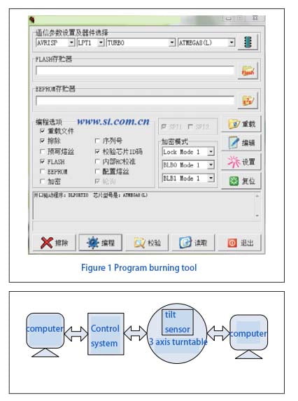
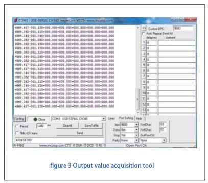
When the test circuit board is made, it is necessary to use the burner and related software to burn the test program in the single chip microcomputer, as shown in Figure 1. The test circuit board with sensor is fixed on the three-axis turntable, and the circuit board is connected to the computer that collects data, so as to form a complete test device, as shown in Figure 2.

tilt sensor complete test device structure diagram

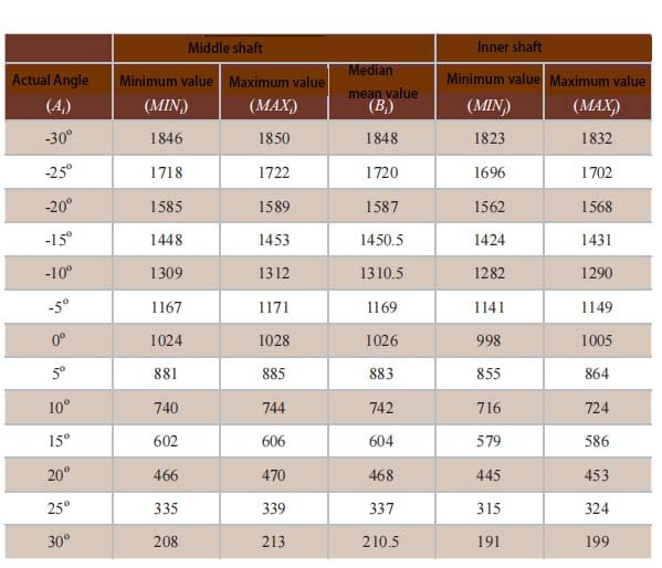
tilt sensor output value acquisition tool

3. Measurement process
After the preparation work is completed, the measurement begins. Along with the rotation of the central axis and the internal axis of the three-axis turntable, the two-axis tilt sensor has the corresponding output value. We collect the data and save it on the computer. After that, the output value is processed, and the output value after data processing is compared with the rotation Angle of the turntable to calculate the accuracy of the sensor. Because the data processing of the central axis and the internal axis is the same, the central axis is introduced here as an example. After many calculations and measurements, the most suitable coefficient is selected to meet the requirements of high precision.
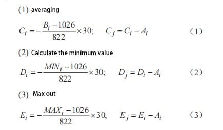
Since the measurement range of the biaxial tilt sensor we selected is between -30℃ and +30℃, here we set the minimum Angle of rotation of the turntable to 5°. Rotation Angle are respectively - 30 °, 25 °, and 20 °, 15 °, and 10 °, 5 °, 0 °, + 5 °, + 10 °, + 15 °, + 20 °, 25 °, 30 ° +, will these values are expressed in Ai. Each time the turntable is rotated, the output value of the sensor is recorded by relevant software, as shown in Figure 3. Among the many output values each time, the minimum and maximum values are recorded, and the data is saved to the computer, as shown in Table 1.

Table 1 Sensor output values

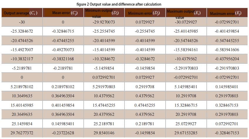
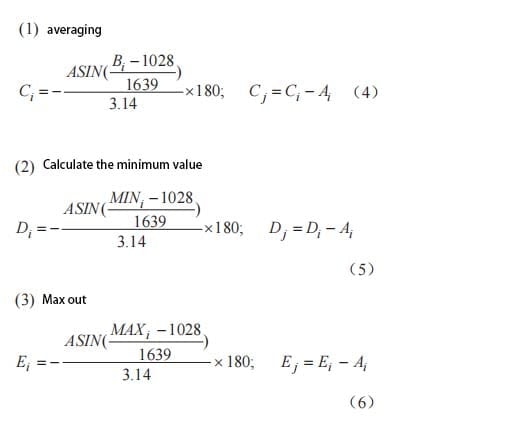
Taking the data at 0° as the benchmark, the output values Ci, Di, Ei and the difference between each output value and the set value Ai Cj, Dj, Ej were calculated using the corresponding formulas

Output value of each formula

The calculated data table is shown in Table 2.

Output value and difference after calculation

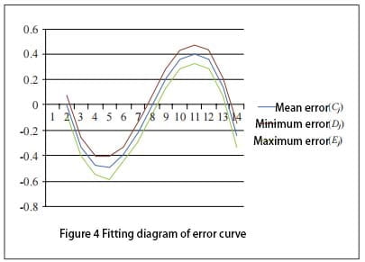
Curve fitting was performed on Cj, Dj and Ej, as shown in Figure 4.

Fitting diagram of error curve

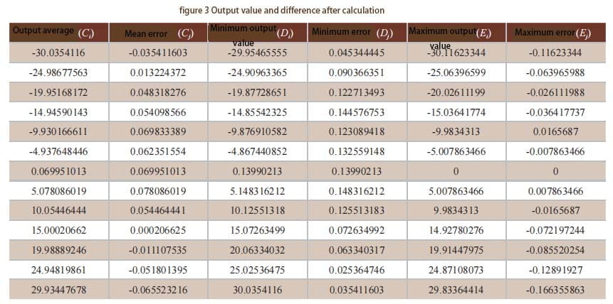
According to the value 1026 corresponding to 0°, the output value is converted into an Angle, the evaluation test and multiple measurements are carried out. Finally, the optimal values 1028 and 1639 are selected, and the output values Ci, Di, Ei and the difference between each output value and the set value Ai Cj, Dj, Ej are calculated by using the corresponding formulas.

The formula value after many measurements

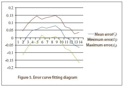
The calculated data table is shown in Table 3. Curve fitting was performed on Cj, Dj and Ej, as shown in Figure 5.

Table 3 Output value and difference after calculation

4 Summary
Through measurement and data processing, the requirements for improved accuracy are finally met. As can be seen from Figure 5, the measurement error of the biaxial inclinometer sensor has reached (-0.15~+0.17). To meet higher requirements, the algorithm needs to be further improved.

Figure 5. Error curve fitting diagram

For our biaxial inclinometer sensors, such as ER-TS-4250VO and ER-TS-4258CU, we can obtain the appropriate correlation coefficient by repeated data processing and comparing the old and new error values in the test through the above algorithm, so as to improve the measurement accuracy of the sensor. 

Tuesday, January 30, 2024

How to Improve Reliability of Tilt Sensors


 1. How to ensure the reliability index of the tilt sensor

For the technical indicators and performance indicators of the tilt sensor, there are usually clear and quantitative index requirements, which can be directly measured and tested when the product leaves the factory. For reliability indicators, it is generally impossible to implement direct measurement and inspection, and it is necessary to carry out reliability design and control of the whole process of product development and production to ensure that the reliability indicators meet the requirements. We mainly discuss the reliability supervision and control, design and evaluation and test of tilt sensor in the development, production and use stage.

2. Reliability design
The development stage of inclinometer sensor can be divided into demonstration stage, scheme stage, development stage and finalize stage. According to the technical requirements of the tilt sensor, the MTBF task value θS of the sensor is determined in the demonstration stage, and the θS is preliminarily demonstrated according to the reliability level of the sensor product.
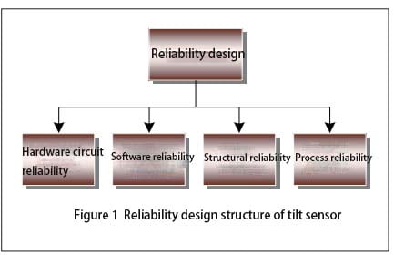
When the inclinometer sensor is in the project stage, it is necessary to design according to the tactical technical index of the inclination sensor and work out the functional block diagram of the sensor. According to the block diagram of tilt sensor, the internal logic relationship in the block diagram is analyzed, and the reliability block diagram of the newly developed inclination sensor is compiled. According to the reliability block diagram of the inclinometer sensor, the reliability indicators are assigned to each subsystem of the sensor, or the reliability indicators on the technical requirements are weighted, and the results after allocation must meet the reliability indicators of the whole system. After the reliability block diagram is prepared and the reliability index is assigned, the estimated reliability value θP is estimated for the components used in the hardware circuit. According to the obtained θP value, the part of the hardware circuit that affects the reliability of the sensor is designed and changed. At last, the functional block diagram, reliability block diagram, reliability distribution index and reliability predicted results prepared according to the technical requirements of the inclination sensor are reviewed periodically in order to improve the design of the defects that affect the reliability of the sensor. In the reliability design of the tilt sensor, the design needs to be considered as shown in Figure 1.

Reliability design structure of tilt sensor

2.1 Reliability design of hardware circuit
After the inclinometer sensor enters the development stage, the hardware circuit is designed according to the functional block diagram and reliability block diagram.
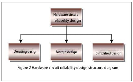
In the design of hardware circuit reliability, the aspects that need to be considered are shown in Figure 2.

Tilt sensor Hardware circuit reliability design structure diagram

In the process of hardware circuit design, components are the basis of circuit reliability design. In the actual sensor hardware circuit, due to different environments, load changes and a series of reasons such as the design of the sensor drift fault, therefore, in the actual design of the hardware circuit should be integrated into the margin design, after the completion of the hardware circuit design, before the data transmission, it is required to check the integrity of the components in the hardware circuit to ensure that the sensor is powered on. Correct and intact data transmission between each unit. In addition, limit testing and reasonableness testing are performed on all analog and digital inputs and outputs in the hardware circuit.
2.2 Software program reliability design
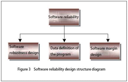
In the design of the hardware interface software of the sensor, the failure detection of the external input or output device must be considered first, and when the failure is detected, the software can restore the interface to a certain safe state, and the hardware failure mode involved is also required to be considered. When the sensor transmits data, in order to ensure the authenticity and reliability of the data received by the receiver, the data sent by the sender is required to use a specific format and content, so that the sender and the receiver can use the agreed method for verification. In the process of software design, its reliability design structure is shown in Figure 3.

Tilt sensor Software reliability design structure diagram

When the software program of the sensor is written, the first thing to consider is the robustness of the software. In software robustness design: First, the power module of the inclinometer sensor may have intermittent failure at the moment of power supply, so that the inclinometer sensor into a potential unsafe state, in order to avoid this state, it is required that the software safely shut down the sensor when the sensor power supply fails, in addition, the power supply of the inclination sensor may have abnormal fluctuations. Software is also required to handle it; Second, the software design must take into account a self-test when the sensor is powered on, verifying that the sensor system itself is safe and can operate normally, and when necessary, the sensor can carry out periodic self-testing; Third, the inclination sensor needs to work normally in electromagnetic radiation, static interference and other environments, which requires the sensor hardware circuit design to be processed according to the technical requirements, so that the sensor can control the external interference within the specified range, when there is external interference, the software is reset again, so that the sensor can still operate normally. Secondly, it is necessary to carry on the margin design when writing the sensor operation program. While ensuring the storage capacity and data channel transmission capacity of each module of the software, the software margin of the inclination sensor should be planned to ensure that the software margin meets the requirements. According to the specific state of each subsystem during software running, the arrangement of various cycles and working time series of software is determined to ensure that sufficient margin is reserved between software working time series.
Finally, consider the data definition when the sensor program is written. When defining the data in the software operation process, it is necessary to ensure that the defined data must be within a reasonable range, so that the sensor can ensure the size and error of the value within the specified range during the data operation process to ensure the accuracy of the data operation. In addition, reasonableness checks are also carried out at the entrance, exit, and other key locations of the software.
2.3 Structural reliability design
In addition to the protection of the external environmental stress, the electromagnetic compatibility of the inclinometer sensor is mainly optimized in the structure of the sensor. Under modern conditions, electromagnetic interference is everywhere, in this environment to make the sensor normal operation, it is required to optimize the sensor in hardware circuit, overall structure, manufacturing process, etc., in order to reduce the sensitivity of the sensor for interference, so that the external entry and internal leakage of electromagnetic interference can be controlled in a acceptable range.
2.4 Process reliability design
Process reliability design is mainly divided into printed board reliability design, electrical interconnection design and “three defenses” design. The reliability design of the printed circuit board requires the layout of the entire circuit board to be reasonable, and a single functional module or functional circuit is placed on a panel as far as possible, which is more convenient for later troubleshooting and maintenance. The circuit board should be rationally arranged on the circuit board, the circuit at all levels should be arranged and combined according to the distribution of the schematic diagram, the input and output of the sensor should be arranged separately, the analog circuit module and the digital circuit module should be isolated, the layout and wiring should be reasonable as far as possible, and the generation of parasitic coupling electromagnetic interference should be suppressed. When placing electronic components on the circuit printed board, it is required to be as suitable as possible for visual inspection of the entire circuit printed board, to facilitate the inspection of the nominal value of electronic components and fault location. When placing large and heavy components on the circuit printed board, it is necessary to reinforce them to prevent damage to components caused by vibration and impact of the sensor and make the sensor unable to operate normally. The design of electrical interconnection requires the sensor process specification to specify the installation and welding temperature and time of the components, the welding specifications of the inserted components and the operating conditions of the welding operators. The “three defenses” design requires the developer to fully understand the use environment of the sensor, master the characteristics of the sensor use environment and the law of change, analyze the stress conditions of the sensor failure in its use environment, and finally choose the suitable defense for the sensor
Enclosures, materials and sensor manufacturing processes.
3 Summary
By analyzing the reliability of inclinometer sensors in the process of development, production and use, we integrate the reliability design of wireless ER-TS-12200-Modbus and single-axis ER-TS-3160VOER-TS-4150VO and other tilt sensors into the development and production of sensors. Through the reliability information collected by customers during the use of such products, the reliability assessment of the sensor is carried out, and the reliability improvement of the tilt sensor is finally completed. 

Thursday, January 25, 2024

Tilt Sensor Automatic Calibration System


Full text: https://www.ericcointernational.com/application/tilt-sensor-automatic-calibration-system.html 

1. Tilt sensor calibration method

Tilt sensor is widely used in the field of engineering measurement, and its measurement accuracy is often related to the evaluation of the deformation of structures, which is of great significance to the construction quality control and safety production management of construction engineering site. The manual two-point calibration method is commonly used to calibrate the inclinometer sensor, which describes the relationship between the output voltage and the Angle through a straight line, and is usually only suitable for the inclination sensor with low accuracy requirements. If the sensor has relatively high accuracy requirements, it is necessary to use a higher precision inclination chip and calibration method. Multi-point calibration is an effective calibration method to improve the accuracy of sensors, but in the case of a large number of fixed points using manual trigger, reading and calculation calibration method, not only low efficiency, and by human factors interference, is not conducive to the large-scale production of sensors. By designing an automatic calibration system for tilt sensor based on programmable electric Angle station, we realize the automatic change of Angle, reading and result output in the calibration process of inclinometer sensor, improve the calibration efficiency and sensor accuracy, and reduce the dependence of the calibration process on the technical level and experience of the operator.

2. Principle of automatic calibration of inclination sensor
The calibration of the sensor means that the measured value of the inclinometer sensor with higher precision is input to the inclination sensor to be calibrated as the standard value, and the feedback value of the sensor to be calibrated is obtained for data fitting processing. The common calibration method only calibrates the inclination sensor by two fixed points, and describes the error Angle relationship of the sensor by a straight line. This method is easy to operate and is suitable for tilt sensors with low precision.
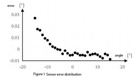
However, if the inclinometer sensor with a measuring range of -15°~+15° collects data every 1°, and the error of each Angle is obtained as shown in Figure 1, it can be found that the error of the sensor is not linear with the Angle when the Y-axis interval is set to 0.01°. Therefore, if the sensor is calibrated by multi-point calibration method, the error of the sensor is not linear with the Angle. The accuracy of the sensor can be further improved by fitting a curve to describe the error characteristics of the sensor.

tilt Sensor error distribution

Therefore, this paper adopts the multi-point calibration method that sets 1 fixed point every 1°, and the third-order fitting method based on the principle of least squares to compensate the sensor error. The error fitting model is as follows:
Δφ = a1x3 + a2 x 2 + a3x + a4 (1)
In the formula, Δφ is the error value of the inclination Angle, x is the acquired value of the sensor to be calibrated, and a1, a2, a3 and a4 are the coefficients of the fitting polynomial.

3.Overall system scheme
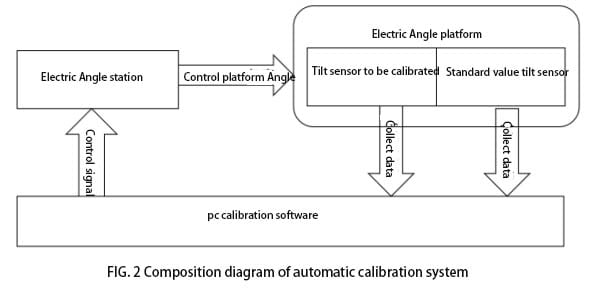
The automatic calibration system is composed of three parts: electric Angle station, standard inclination sensor and PC calibration software, as shown in Figure 2.

tilt sensor Composition diagram of automatic calibration system

During calibration, the tilt sensor to be calibrated and the standard value sensor are fixed parallel to the electric Angle platform, the electric Angle platform is connected to the PC calibration software using RS485, and the tilt sensor to be calibrated and the standard value sensor are connected to the PC calibration software through the RS232 of the lora module at the receiving end. The calibration software at the PC end sets the Angle of the fixed point, the calibration software automatically controls the electric Angle station to find the corresponding fixed point, and continuously collects data at each fixed point to analyze whether the Angle data of the tilt sensor and the standard value sensor to be calibrated is stable (the difference between the last 10 sets of data collected does not exceed 0.003°). Record the readings of the tilt sensor and the standard value sensor to be calibrated, and automatically rotate to the next set point until all 31 set points are collected, and the software automatically calculates each parameter of the fitted curve according to the collected data.

4. System testing and analysis
4.1 Functional Testing
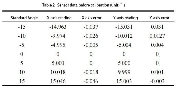
In order to verify the function of the automatic calibration system, an inclination sensor with a factory accuracy of 0.1° was placed in the system for calibration. The resulting data are shown in Table 2.

tilt Sensor data before calibration

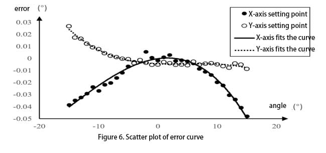
It can be seen from Table 2 that before calibration, the maximum error of the sensor X axis is -0.037°, and the maximum error of the Y axis is 0.031°. The error fitting curve of the sensor calculated by the calibration software is shown in Figure 6.

tilt sensor-Scatter plot of error curve

4.2 Accuracy Verification
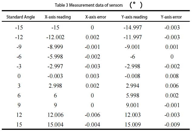
In order to verify the accuracy of the calibrated sensor, the automatically calibrated inclination sensor is sent to a professional measuring institution for measurement. The measurement accuracy is required to be 0.01°, and the measurement data are shown in Table 3.

Measurement data of tilt sensors

The measurement results show that the maximum error of X axis and Y axis is 0.006° and 0.009°, respectively, satisfying the accuracy index of 0.01°. The accuracy of the sensor is improved by one order of magnitude after calibration by the automatic calibration system.
5.Conclusions
We demonstrate the design direction of an automatic calibration system for inclinometer sensor, and carry out the calibration and performance test of the system. During the design and implementation of the automatic calibration system, the following conclusions are obtained:
(1) The automatic calibration system based on the programmable electric Angle station can realize the automatic calibration of the inclinometer sensor, effectively improve the calibration efficiency and save labor costs.
(2) The selection of the resolution of the electric Angle station should fully consider the mechanical structure characteristics of the Angle station. Compared with the resolution of 0.007° and 0.00036°, the resolution of 0.0007° can ensure the calibration accuracy while having higher calibration efficiency. The resolution of the ER-TS-12200-Modbus is 0.0005°, and the resolution of the ER-TS-22800 is 0.0008°, so the ER-TS-22800 can achieve higher calibration efficiency while ensuring calibration accuracy.
(3) The experimental results show that compared with the traditional two-point calibration method, using the multi-point calibration method to calibrate the inclinometer sensor and using the third-order curve to fit the error characteristics of the sensor can effectively improve the accuracy of the inclinometer sensor.  

Wednesday, January 24, 2024

Tilt Sensor Automatic Calibration System


Full text: https://www.ericcointernational.com/application/tilt-sensor-automatic-calibration-system.html

1. Tilt sensor calibration method

Tilt sensor is widely used in the field of engineering measurement, and its measurement accuracy is often related to the evaluation of the deformation of structures, which is of great significance to the construction quality control and safety production management of construction engineering site. The manual two-point calibration method is commonly used to calibrate the inclinometer sensor, which describes the relationship between the output voltage and the Angle through a straight line, and is usually only suitable for the inclination sensor with low accuracy requirements. If the sensor has relatively high accuracy requirements, it is necessary to use a higher precision inclination chip and calibration method. Multi-point calibration is an effective calibration method to improve the accuracy of sensors, but in the case of a large number of fixed points using manual trigger, reading and calculation calibration method, not only low efficiency, and by human factors interference, is not conducive to the large-scale production of sensors. By designing an automatic calibration system for tilt sensor based on programmable electric Angle station, we realize the automatic change of Angle, reading and result output in the calibration process of inclinometer sensor, improve the calibration efficiency and sensor accuracy, and reduce the dependence of the calibration process on the technical level and experience of the operator.

Tuesday, January 23, 2024

Influence of Ambient Temperature on Measurement Data of Tilt Sensor


For the full article, click here https://www.ericcointernational.com/application/influence-of-ambient-temperature-on-measurement-data-of-tilt-sensor.html

1. How to reduce the impact of ambient temperature on the tilt sensor?

At present, the tilt sensor is widely used to measure the inclination Angle of various structures, such as foundation pit, slope, dam, railway system, etc., which can reflect the stability and safety of the structure. Temperature will affect the inclinometer sensor, which is the cause of the fluctuation of the measurement data of the inclinometer sensor. At present, the influence of ambient temperature on the measurement of the tilt sensor can be reduced by improving the hardware of the inclination sensor, such as changing the temperature of the heat source inside the sensor, adding the temperature compensation circuit, etc., but this method is more expensive and less accurate than the method that considers the relationship between the measurement data and the change of ambient temperature to establish the temperature compensation formula. Moreover, most of the measurements of inclination sensors are tested in the laboratory, and the sensor with temperature compensation function is redesigned according to the measurement results in the laboratory, which is different from the application of inclination sensors in practical engineering. Therefore, we analyze the inclination sensor data measured in the actual engineering environment, and establish the temperature compensation formula with appropriate fitting method, so as to reduce the influence of ambient temperature on the inclination sensor measurement data.

2. Principle of influence of temperature on measurement data of inclination sensor
We set up an inclinometer sensor on a slope that needs to be monitored and use an automated monitoring platform to collect and receive sensor data in real time. We analyzed the original data of the inclination sensors extracted from July 15 to August 15, 2022, and the analytic results of part of the inclination sensors are shown in Figure 1.
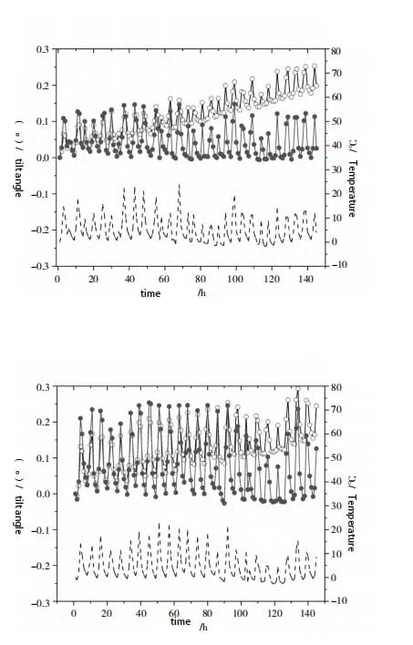
tilt sensor data changes

As can be seen from Figure 1, the inclination of Angle X and Angle Y of the inclinometer sensor is significantly affected by temperature. The higher the ambient temperature is, the greater the data inclination Angle is. Moreover, Angle X is significantly affected by temperature than Angle Y, indicating that the ambient temperature has a greater impact on the output of the signal of the inclination sensor. The inclination sensor has a large temperature fluctuation error due to the change of ambient temperature in practical application. This is because under the influence of temperature, there will be some changes in the parameters of the devices in the sensor, which will affect the measurement accuracy and reliability of the sensor. Therefore, it is necessary to consider the influence of ambient temperature on the data, and establish the temperature compensation formula according to the actual measurement data of the inclination sensor, so as to correct the measurement data of the inclination sensor.

3. Establishment of temperature compensation formula
First, the influence range of temperature should be determined. As can be seen from Figure 1, the X Angle of inclinometer sensors 01 and 02 basically has no deviation during the period from July 15, 2022 to August 15, 2022. The data measured by inclination sensors 03 and 04 are analyzed. Moreover, the relative offset of X Angle of each sensor is less than ±0.025° (indicating that the floating error caused by temperature is small). The results are shown in Table 1.

Tilt sensorTemperature range
0126~31
0226~30
0326~33
0426~30

As can be seen from the statistical data in Table 1, when the inclination sensor is at (28±2) ℃, it can be seen from Figure 1 that the inclination degree of the inclination sensor X Angle and Y Angle is significantly affected by temperature. The higher the ambient temperature is, the greater the data inclination Angle is, and the influence of temperature on X Angle is more obvious than that of Y Angle. It shows that the ambient temperature has a great influence on the output of the inclinometer sensor signal, and the inclination sensor has a great temperature fluctuation error in practical application due to the change of ambient temperature. This is because under the influence of temperature, there will be some changes in the parameters of the devices in the sensor, which will affect the measurement accuracy and reliability of the sensor. Therefore, it is necessary to consider the influence of ambient temperature on the data, and establish the temperature compensation formula according to the actual measurement data of the inclination sensor, so as to correct the measurement data of the inclinometer sensor.
Moreover, it can be seen from Figure 1 that there is a linear relationship between the influence of temperature on the output value of the inclination sensor signal, and the following linear temperature compensation formula can be established:

X1=X0-A×(T-28) (1)

Y1=Y0-A×(T-28) (2)

Where: X0 is the original output value of X Angle of the inclination sensor, (°); Y0 is the original output value of the Angle Y of the inclination sensor, (°); X1 is the tilt Angle of the corrected X Angle, (°); Y1 is the tilt Angle of the corrected Y Angle, (°); T is the ambient temperature value output by the inclinometer

sensor, (°); A is the temperature compensation coefficient; A×(T-28) is a ring
Output increment due to ambient temperature. The size of the temperature compensation coefficient A is constantly adjusted to obtain better compensation effect, and the proportional coefficient of the temperature compensation coefficient A of each inclination sensor is finally obtained, as shown in Table 2.

Tilt sensorThe scale coefficient of A
X AngleY Angle
010.0070.004
020.0130.008
030.0050.004
040.0100.004

4. Analysis of temperature compensation effect
The results of X Angle and Y Angle corrected by the temperature compensation formula are shown in Figure 2. As can be seen from FIG. 2, the fluctuation of X Angle and Y Angle under the influence of temperature change after being corrected by the temperature compensation formula becomes significantly smaller. The variance of X Angle data of tilt sensor 01 is 0.001 950, and the modified variance is 0.000 169. The X-angle data variance of tilt sensor 02 is 0.00 648, and the corrected variance is 0.000 493. It can be seen from the above that the X and Y angles corrected by the temperature compensation formula are affected by the temperature change, and the fluctuations generated are reduced by one order of magnitude, indicating that equations (1) and (2) can effectively weaken the influence of ambient temperature on the measurement of the inclination sensor, improve the measurement accuracy of the inclination sensor, and meet the measurement needs of the actual environment.
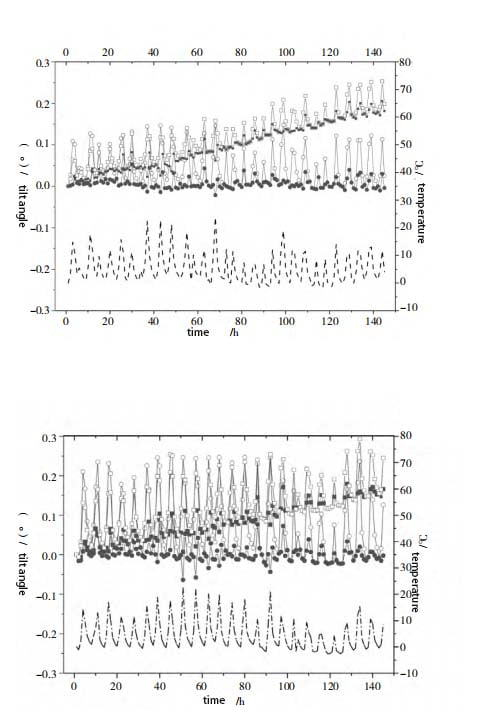
Temperature compensation for the change in inclination

From the temperature difference of 1.5 ° C, 20 different grades of temperature are selected in the operating temperature range of the inclination sensor -20 ~ 70 ° C for testing. According to the annual temperature difference of about 30 ° C in Guangdong Province, the inclination sensor is put into the temperature control box. Starting from 5 ° C, the temperature difference interval of 1.5 ° C is heated. Keep heating up to 35 ° C and observe the data change. 7 different levels of pressure are selected from the range of -15° ~ 15° of the inclination sensor. Considering the basic level of the initial Angle when the inclination sensor is installed, the maximum installation inclination Angle does not exceed 10°, the cumulative variation given by the design unit of the project does not exceed 60 mm, and the maximum height of the slope is 10 m. According to the trigonometric function, the Angle is 0.35°, so the maximum Angle of the test is 12°. Then a test is performed every 4° from -12° to 12°, and the X and Y directions are involved in the test, with a total of 280 data. MATLAB software is selected to realize the verification and analysis of the model. The accuracy of the maximum relative error is verified by the formula as follows:

Error formula verification of tilt sensor


The results show that when the inclination is 10.5° and the temperature difference is 30 °, the error reaches 0.3°. After compensation, the maximum error is better than 0.01°; The maximum error before compensation is 12% and the maximum error after compensation is 0.15%. The compensation effect is good.

5 Summary
We study the influence of temperature on the measurement accuracy of the inclination sensor, and find that the inclination sensor has a large temperature fluctuation error due to the change of ambient temperature in practical application. In order to reduce the influence of the ambient temperature on the measurement accuracy of the inclination sensor, the temperature compensation formula is established based on the actual measurement data of the inclination sensor, and the relationship between the measurement data and the ambient temperature is fully considered. The main conclusions are as follows:
(1) The ambient temperature has a significant effect on the inclination sensor, and the higher the temperature, the greater the measurement error. Moreover, the temperature compensation coefficients of each inclination sensor are different, indicating that different inclination sensors are affected by temperature to different degrees.
(2) The error of X Angle and Y Angle measured by the inclination sensor is different under the influence of temperature, and the error of X Angle under the influence of temperature is larger than that of Y Angle. For example, ER-TS-12200-Modbus is a dual-axis monitoring system. In actual measurement, the error is different due to the influence of temperature. The error of X Angle due to the influence of temperature is larger than that of Y Angle.
(3) Considering the relationship between the measurement data and the change of ambient temperature, the temperature compensation formula is established and applied. The results show that the proposed temperature compensation formula can effectively reduce the influence of ambient temperature on the measurement accuracy of the inclination sensor.
Although it is greatly affected by the ambient temperature, such as our ER-TS-32600-Modbus and ER-TS-4250VO, temperature compensation formulas can be established to effectively correct and apply their measurement data, so as to reduce the impact of ambient temperature on the measurement accuracy of the sensor. 

Tuesday, January 16, 2024

Research on Temperature Characteristics of Tilt Sensor


1. Influence of temperature on tilt sensor

Tilt sensor is widely used in various angle measurement, such as high precision laser instrument level, ship navigation attitude measurement, geological equipment tilt monitoring, satellite communication vehicle attitude detection. However, in the harsh working environment, the inclination sensor is easily affected by temperature, and there are zero point and sensitivity temperature drift.
Because the temperature of the working environment of the tilt sensor changes greatly, and the heat output caused by the temperature change will bring large measurement errors. At the same time, temperature changes also affect the size of zero and sensitivity values, and then affect the static characteristics of the sensor, so measures must be taken to reduce or eliminate the impact of temperature changes, that is, temperature compensation must be carried out.

2. Tilt sensor temperature compensation method
Inclination sensor temperature compensation methods are generally divided into hardware compensation method and software compensation method. Hardware compensation method is mainly achieved by changing device structure, material, working environment and technology to improve the reliability of measurement results. But in practical application, the working environment is bad, the structure of hardware compensation method is complicated and it is difficult to achieve the ideal effect. The idea of software compensation is to separate and compensate the error through experiment. Because the temperature error of tilt sensor is a nonlinear error, it is difficult to achieve a high compensation accuracy. RBF neural network has strong curve fitting ability. Compared with BP neural network, we use RBF neural network for temperature compensation of inclinometer sensor, which greatly reduces the influence of temperature on tilt sensor and achieves good compensation effect.

3. Temperature compensation based on radial basis function RBF neural network
3.1 RBF neural network compensation principle
RBF neural network is a kind of forward feedback-free network with excellent performance. It can approximate continuous function with arbitrary precision and has been widely used in pattern recognition, function approximation and so on. RBF neural network is composed of input layer, hidden layer and output layer. The hidden layer nodes are composed of Gaussian radial basis functions, as shown in equation (1) :

tilt sensor-Gaussian radial basis function

i=1,2,…,h (1)Where: ci is the center of the i-th basis function and has the same dimension as x; σi is the extension constant or width of the i-th basis function, and the smaller σi is, the smaller the width of the radial basis function and the more selective the basis function is. Neurons in the output layer adopt a linear activation function, and the output of the KTH neuron is shown in equation (2) :

Tilt sensor-output of the KTH neuron

Where: yk is the output of the KTH neuron in the output layer; W2ik is the connection weight of the I-th neuron in the hidden layer and the K-th neuron in the output layer.
In the parameter design of RBF neural network learning algorithm, it is generally necessary to design three parameters: data center of each basis function, expansion constant and weight of output node. We use K clustering algorithm to determine the basis function of the data center. Recursive least square method is used for the weight between hidden layer and output layer to ensure faster convergence speed.

3.2 RBF neural network temperature compensation results
In the simulation experiment, the output value T1 of the inclination sensor and the temperature of the temperature box are taken as the input of the model, and the rotation Angle of the tilt sensor is taken as the output of the model. The 100 sets of data in the following table are samples of the RBF neural network two-input-output model.

Tilt sensor temperature experiment data recording

The input layer of the neural network is composed of two neurons, and the output layer is composed of one neuron. The number of hidden layer neurons is automatically added by the software through checking the output error until the error requirement or the maximum number of hidden layer neurons is reached. Through several experiments, the radial basis function distribution density SPREAD=0.5 and the training target error was set as EGOAL=1e-6. After 25 training sessions, the target training accuracy was achieved. Compensation results are shown in the following table.

tilt sensor-RBF neural network temperature compensation results1

tilt sensor-RBF neural network temperature compensation results

The output RBF neural network modeling graph is shown in the following figure

tilt sensor-Neural network fitting effect

Comparing Table 1 and Table 2, it can be seen that the temperature drift and full scale error of each axis are greatly reduced after modeling by RBF neural network. As can be seen from the RBF network fitting effect diagram in FIG. 3, the simulation graphics transition smoothly at each point, and the model compensation effect is relatively ideal. In order to compare the compensation effect of the RBF network, we also set up the BP neural network compensation model which is often used for temperature compensation. The input layer of BP neural network is composed of two neurons and one implicit layer. After many experiments, it is determined that the optimal number of hidden layer is 5, and the output layer is composed of 1 neuron. The goal error of the training is EGOAL=1e^(-4), and the learning efficiency is LP.lr=0.2. In the experiment, 100 groups of samples in Table 1 were used to train the established BP network. After about 50 iterations, the training was completed. The training pairs of RBF and BP network were shown in the following figure.

Tilt sensor-Comparison of RBF and BP neural network training

The target difference of BP neural network training is 1e^(-4), and that of RBF neural network training is 1e^(-6). However, the training time of RBF neural network is only about 1/2 of that of BP network, which shows that RBF convergence speed is relatively ideal. At the same time, the zero point temperature drift and sensitivity temperature drift before and after compensation are shown in following table. BP network and RBF network reduce the zero point and sensitivity temperature drift by 1 and 2 orders of magnitude respectively. The full scale error diagram of the inclination sensor under the action of -20~70℃ is shown in the figure below.

the zero point temperature drift and sensitivity temperature drift before and after compensation

full scale error diagram of the inclination sensor under the action of -20~70℃

The maximum full scale error before compensation is about 2.34%, after BP neural network modeling compensation is about 0.85%, and after RBF modeling compensation is reduced to 0.158%. The simulation results show that the output error of the tilt sensor decreases after temperature compensation, and the output error decreases from 2.8° before compensation to 0.23° after conversion to angle degree. The modeling effect of RBF neural network is much better than that of BP network model, and it is very close to the actual expected value. Therefore, for the inclination sensor in this paper, RBF neural network modeling compensation can obtain better compensation effect.

Concluding discussion
We use RBF neural network compared with BP network to realize the research of temperature compensation of inclination sensor. The experimental results show that the RBF neural network modeling compensation achieves good compensation results in this system: for zero temperature drift, the X-axis decreases from 1.61×10^(-4) before compensation to 7.41×10^(-6), and the Y-axis decreases from 1.94×10^(-4) before compensation to 5.56×10^(-4). For sensitivity temperature drift, the X-axis decreased from 2.05×10^(-4) before compensation to 5.56×10^(-6), and the Y-axis decreased from 1.84×10^(-4) before compensation to 4.63×10^(-6). The RBF neural network is used to compensate the temperature of the inclinometer sensor, which reduces the influence of temperature on the sensor, overcomes the disadvantage that BP network is easy to fall into local optimal, improves the stability and measurement accuracy of the system, and lays a foundation for the application of the inclination sensor in various industries.

For example, Ericco’s ER-TS-12200-Modbus and ER-TS-32600-Modbus, both of which are dual-axis monitoring, we can completely carry out temperature compensation through RBF neural network modeling, and after compensation, the zero temperature drift and sensitivity temperature drift value of X axis and Y axis will be greatly reduced. In this way, we can reduce or even eliminate the adverse effects of temperature on the inclinometer sensor. 

Choose a suitable IMU to make your drone flight more stable and safe

         As one of the core components of drones, IMU plays an irreplaceable role. Its high precision, fast response and freedom from extern...