Monday, May 31, 2021

How to use IMU (inertial measurement unit )in pipeline 3D attitude measuring ?

Inertial navigation is an inertial measurement unit (IMU) composed of a gyroscope and an acceleration sensor to measure angular velocity and acceleration information of the carrier.Based on the inertial measurement principle, the pipeline attitude measuring instrument introduced in this paper measures its own three-axis attitude Angle or angular velocity, current acceleration, etc., and analyzes and calculates these attitude quantities, so as to obtain the three-dimensional attitude of the pipeline.

.Let's take a look a measuring instrument based on inertial measurement sensor technology -- pipeline three-dimensional attitude measuring instrument.

As a common instrument for measuring the precise attitude (trajectory) of underground pipelines, the pipeline attitude measuring instrument is a kind of three-dimensional precise attitude measuring instrument based on MEMS inertial measurement unit.This kind of product has internal integration of inertial guided measurement unit, lithium battery, DSP and mass storage unit, which can complete the collection without external auxiliary equipment. It adopts all-metal sealing structure and adaptive shrinkage guide device, which can adapt to the traction and travel of various inner diameter pipelines. It is shockproof and always keeps the measuring unit on the center line of the pipeline.It is mainly applied to the completion measurement of pipe jacking construction in trenchless industries of underground pipelines such as electric power, gas and water.

In the process of use, the pipeline attitude measuring instrument can measure its own three-axis attitude Angle or angular velocity, current acceleration and travel distance through the inertial measurement sensor device. These attitude values are analyzed and calculated by the integral algorithm, so as to obtain the three-dimensional attitude of the pipeline.In complex urban environment, this kind of instrument can accurately measure the three-dimensional data of underground pipeline, which is especially suitable for the measurement and positioning of pipeline completion.

At present, the existing pipe network and well chamber detection technology includes ground detection and underground detection. Ground detection is mainly carried out by radar, infrared ray and ultrasonic methods for line finding and flaw detection.Although the detection is conducted directly on the surface, the detection efficiency is low and the detection accuracy cannot be guaranteed. At the same time, there are certain requirements for the technical level of the detection personnel and the cost of the detection equipment is also relatively expensive.Underground detection technology consists of laser radar, closed-circuit television, downhole robot: although laser radar theory can more accurate detection of pipe network, but to the well chamber test is difficult, expensive equipment at the same time, inconvenience, for operating and testing personnel requirements are high, the result is not intuitive, practicality is not high.


For trenchless pipeline of accurate location information in pipeline construction, the scientific use of underground space, the maximum to avoid the line cut, eliminate the potential accidents, by adopting pipeline three-dimensional attitude measuring instrument, to the trenchless pipeline in pipeline construction to carry on the accurate measurement and positioning, so as to solve the above other detection means can't solve the practical problems.

It should be noted that, in practical application, because the pipeline 3D attitude measuring instrument is based on the principle of accurately measuring its own motion trajectory and obtaining the central coordinate sequence of the measured pipeline, its measurement accuracy is not only limited by the built-in core inertial sensor measurement unit, but also closely related to the structural stability of the instrument during operation.Therefore, keeping the structure of the measuring pipe stable is also one of the prerequisites for accurate data measurement by the 3D attitude measuring instrument .


IMU in UAV (MEMS three-axis accelerometer, three-axis gyroscope, three-axis magnetometer)

3-axis accelerometer

(1) Measurement of specific force

A triaxial accelerometer is an inertial sensor that measures the specific force of an object, the overall acceleration without gravity or the non-gravitational force applied per unit mass.When the accelerometer stands still, the accelerometer senses the acceleration of gravity, and the overall acceleration is zero.In free fall, the overall acceleration is the acceleration of gravity, but the internal acceleration of the accelerometer is weightless, and the output of the three-axis accelerometer is zero.   


  • (2) Measurement Angle


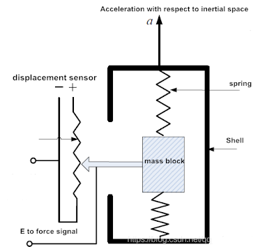
The principle of a triaxial accelerometer can be used to measure angles.Intuitively, as shown in the figure, the amount of spring compression is determined by the Angle of the accelerometer to the ground.The specific force can be measured by the compression length of the spring.Therefore, in the absence of external force, the accelerometer can accurately measure the pitch Angle and roll Angle with no cumulative error.


MEMS three-axis accelerometer is based on piezoresistive, piezoelectric and capacitive working principles, and the specific force (pressure or displacement) generated is proportional to the change of resistance, voltage and capacitance respectively.These changes can be acquired by the corresponding amplifier and filter circuits.The disadvantage of the sensor is that it is greatly affected by vibration.

Because of the working principle of its measuring Angle, the triaxial accelerometer cannot measure the yaw Angle

  • Pitch Angle and roll Angle can be measured


pitching angle


pitching angle

Three-axis gyroscope

Function: Used for the calculation of angular velocity and Angle after integration of angular velocity in UAV

Principle: To understand the principle of a three-axis gyroscope, the first thing to know is the Coriolis force

Coriolis forces

When a particle moves in a straight line with respect to an inertial frame, because of its inertia, it follows a curve with respect to a rotating frame.Based on the rotation system, we think that there is a force driving the particle trajectory to form a curve.The Coriolis force is a description of this shift, expressed as


In other words, when the motion of a straight line is placed in a rotating system, the trajectory of a straight line will be offset. In fact, the motion of a straight line is not affected by the force. This virtual force is called the Coriolis force.


Therefore, we choose two objects in the gyroscope. They are in constant motion, and the phase difference of their motion is -180 degrees, that is, the two mass blocks move in opposite directions with the same size.They produce opposite Coriolis forces, which force the two corresponding capacitor plates to move, resulting in a capacitance difference change.The change in capacitance is proportional to the angular velocity of rotation.The change of rotation Angle can be obtained by the capacitance.

Triaxial magnetometer

The magnetometer provides data on the magnetic field that the device is subjected to along the XYZ axis. This data is then fed into the microcontroller's algorithm to provide the heading Angle associated with the magnetic North Pole. This information can be used to detect geographic position.

The magnetometer uses three mutually perpendicular magnetoresistance sensors, and each axial sensor detects the strength of the geomagnetic field in that direction.

An alloy material with a crystalline structure is shown in the figure above.They are very sensitive to the external magnetic field, the strength of the magnetic field will lead to changes in the resistance value of the reluctance sensor.

In addition, the triaxial magnetometer can also use the Lorentz force principle, the current flows through the magnetic field to generate force, thus driving changes such as capacitance.


How to choose an electronic compass ?

There are a lot of people in the choice of electronic compass do not know how to choose, sometimes because did not consider the following content, and choose the wrong electronic compass, resulting in a waste of time and money, let us to see some tips when choose an electronic compass. 

First, let's take a look at what an electronic compass, also known as a digital compass, is a way of locating the North Pole using the geomagnetic field.

Secondly, as an important navigation and orientation tool, electronic compass is increasingly used in navigation and orientation systems.Most current navigation systems use an electronic compass to indicate direction.The electronic compass can accurately output Azimuth, pitch, Roll and other parameters by calculating the earth's magnetic field and gravitational field.

Known the basic concept of the electronic compass, now let's take a look at the electronic compass types on the market, manufacturers, many models, in the face of these we may look confused, so how to distinguish the performance of the electronic compass, how to choose a suitable for your application of the electronic compass?What's the difference between a good compass and a bad compass?

The main difference between electronic compasses is the difference in accuracy, namely the accuracy of heading, pitch and roll, and especially the accuracy of heading.The heading is defined as the Angle between the projection of the compass's axis on the horizontal plane and the north direction, the pitch is defined as the Angle between the compass's axis and the ground plane, and the roll is defined as the Angle at which the compass rotates about its axis.As shown in the figure below

According to the above definition, if the compass changes only in pitch, then its output azimuth and roll Angle should remain the same.In the same way, if a compass rolls about itself, that is, on its axis, the azimuth and pitch angles of its output should remain the same.In the use of compass, such as used in vehicles, antenna orientation and surface buoys and many other occasions, the carrier will often tilt back and forth, when used in petroleum, geological logging, often rotation, so most applications require compass to meet the requirements of tilt and roll orientation will not change.
Another requirement for compass accuracy is that the output of the compass should be 0 degrees if the current carrier is pointing north, and 90 degrees if the carrier is pointing east. The measured value and the true value should match exactly within the margin of error

For petroleum, geological, and coal logging, the orientation and inclination of the product should not change as the logging instrument rotates downhole, which is important for logging applications.
Another rule when choosing a compass is whether it is resistant to harsh conditions.A natural disadvantage of compasses is that they become less accurate in environments with magnetic interference.Compasses use the direction of the Earth's magnetic field to determine orientation. If the Earth's magnetic field is disturbed or distorted, the accuracy of orientation measurement will be reduced.Iron materials, batteries, motors, high currents, and so on can interfere with the geomagnetic field, and the closer these materials are to the compass, the worse the interference is.So if you want the compass to be accurate, you have to stay away from the source of the interference, but in many cases this is not possible.So the only way to solve this problem is to do magnetic calibration.In the process of magnetic calibration, the compass rotates with the measured object (i.e., the interference source) in a certain way and learns the surrounding magnetic environment to distinguish which is magnetic interference and which is geomagnetic field. Through this learning, the interference is eliminated and the high-precision azimuth output is obtained.


How is the application of 3-axis electronic compass in pipeline monitoring?

 The 3-axis electronic compass can help us to know the precise location of the pipeline.

In recent years, with the acceleration of urbanization, there are more and more underground pipe networks in cities, which brings with it frequent problems.This is because the pipeline is laid in a buried way. When the pipeline runs for a period of time, there are often some defects in the external anti-corrosion system, which causes the chemical corrosion and electrochemical corrosion of the pipeline, thus causing the pipeline corrosion perforation, stress corrosion cracking and other accidents.

Therefore, in order to ensure the safety of the pipeline and reduce the occurrence of accidents, it is necessary for us to monitor the pipeline to ensure the normal application of the pipelin

Pipeline monitoring requires monitoring of a lot of data, including monitoring of pipeline direction, deformation, corrosion, crack, pipeline environment and other key pipeline data.In the whole monitoring process, the precise positioning of the pipeline is a very important part, for example, when we detect deformation, corrosion and other problems, we need to know the specific position of the pipeline problem before the deformation, corrosion and other repairs.

The use of the 3-axis electronic compass can help us to know the precise location of the pipeline.

  • The composition and working principle of 3-axis electronic compass

The 3-axis electronic compass consists of a 3-D reluctance sensor, a biaxial inclination sensor and an MCU, which can locate the direction and measure the inclination.

The three dimensional reluctance sensor is used to measure the earth's magnetic field. The inclination sensor compensates when the magnetometer is not horizontal. The MCU processes the signals from the magnetometer and inclination sensor as well as the data output and the soft and hard iron compensation

The geomagnetic field is a vector, and for a fixed location this vector can be decomposed into two components parallel to the local level and one component perpendicular to the local level.If the electronic compass is kept parallel to the local horizontal plane, then the three axes of the compass magnetometer correspond to these three components.


The three dimensional reluctance sensor uses three mutually perpendicular reluctance sensors, each axial sensor detects the strength of the geomagnetic field in that direction.

The forward direction is called the x-direction sensor to detect the vector value of the geomagnetic field in the x-direction;

Right - or Y-oriented sensors detect the vector value of the geomagnetic field in the Y direction;

The downward or z-direction sensor detects the vector value of the geomagnetic field in the z-direction

The sensor sensitivity in each direction has been adjusted to an optimal point according to the component vector of the geomagnetic field in that direction and has a very low transverse sensitivity.The analog output signal generated by the sensor is amplified and sent to MCU for processing. Combined with the dip Angle data measured by the biaxial dip Angle sensor, the error is reduced and the azimuth is finally determined.

3 axis electronic compass application in pipeline monitoring

As can be seen from the above, the 3-axis electronic compass can locate the direction and measure the inclination Angle, and can be used in pipeline monitoring.However, the 3-axis electronic compass is not directly used. In general, it will be used as a real-time pipeline trajectory detector.The pipeline trajectory detector consists of single chip microcomputer, electronic compass and rotary encoder, etc., which can detect the azimuth Angle, pitch Angle and distance between measuring points of the pipeline in real time, and reconstruct the pipeline trajectory in real time through software algorithm.


3D electronic compass used in pipeline 


High-precision IMU is coming to help in the fields of land, sea and air

  High-precision IMU is now widely used in many fields of sea, land and air. It can provide real-time and accurate information on the carrie...