Thursday, March 31, 2022

How MEMS ‘accelerate’ North Finder


Wednesday, March 30, 2022

The Development Potential of MEMS Sensors

MEMS technology was first conceived in 1959 by Richard Pfeynman (who won the Nobel Prize in Physics in 1965). In 1962, the silicon miniature pressure sensor came out.​​

In 1979 Roylance and Angell began the development of piezoresistive microaccelerometers. In 1991 Cole began the development of capacitive micro-accelerometers.​​

Inertial sensors include accelerometers (or accelerometers) and angular velocity sensors (gyroscopes) and their single-, dual-, and triple-axis combined IMUs (inertial measurement units), AHRS (attitude reference systems including magnetic sensors).​​


The MEMS accelerometer is a sensor that uses the inertial force measurement of the sensing mass, and is generally composed of a standard mass (sensing element) and a detection circuit. According to different sensing principles, there are mainly piezoresistive, capacitive, piezoelectric, tunnel current, resonance, thermoelectric coupling and electromagnetic.​​

In 1998, the US CSDL designed and developed the earliest MEMS gyroscope. In the same year, the Drapor laboratory developed another form of MEMS gyroscope. The MEMS gyroscope is made by using the principle of the Coriolis effect when the vibrating mass is rotated by the base (shell) to sense the angular velocity. The main form is frame drive Type (both inner and outer frame) comb drive type, electromagnetic drive type, etc.​​

Low-precision MEMS inertial sensors are mainly used in mobile phones, game consoles, music players, wireless mice, digital cameras, PDs, hard disk protectors, smart toys, pedometers, anti-theft systems, GPS navigation and other portable products as consumer electronic products. Due to the basic measurement functions such as acceleration measurement, tilt measurement, vibration measurement and even rotation measurement, consumer electronics applications to be explored will continue to emerge.​​

Intermediate MEMS inertial sensors, as industrial-grade and automotive-grade products, are mainly used in automotive electronic stability systems (ESP or ESC) GPS-assisted navigation systems, automotive airbags, vehicle attitude measurement, precision agriculture, industrial automation, large medical equipment, robots, Instrumentation, construction machinery, etc. For example, ERICCO’s high-precision MEMS inertial sensors, as military-grade and aerospace-grade products, mainly require high accuracy, full temperature range, and shock resistance. It is mainly used for stability applications such as communication satellite wireless, UAV navigation, directional drilling and mining, and optical aiming systems; control applications such as aircraft flight control, attitude control, yaw damping, etc., as well as guidance applications such as automatic driving and inertial GPS navigation, remote Aircraft, ships, instruments, robots, etc.


How MEMS inertial sensors work

MEMS inertial sensors are based on integrated circuit technology and micromachining technology, and are manufactured on single crystal silicon wafers. The working principle of MEMS inertial sensor is Newton’s law in classical mechanics. Its function is to measure the center of mass motion and attitude motion of moving objects (such as vehicles, aircraft, missiles, ships, artificial satellites, etc.), and then can control and navigate moving objects. Compared with non-MEMS inertial devices, the size and price of MEMS inertial devices can be reduced by several orders of magnitude, which is of great strategic significance for national defense and large-scale mining drilling. The construction of low-cost, high-performance miniature inertial navigation systems based on MEMS inertial devices is becoming a research hotspot in the field of inertial technology.

Testing of MEMS Inertial Sensors

The test of the MEMS inertial sensor is different from the general IC test in that it requires external stimulation, so in addition to the common configurations such as automated test equipment (ATE), ATE interface board (DIB) and device nest board (DUT board), it also needs An extremely important device – the device that generates and delivers the stimulus. The device is customized, and different sensors, especially different types of sensors, are used differently, or even completely different. Therefore, such devices are often not standardized in the industry, and customers must develop corresponding devices together with device manufacturers while designing new inertial sensors. The cost of this development is very expensive, in the millions of dollars. Even if the sensor package shape is changed, the test surface or cavity must be redesigned, which typically costs $200,000 and 8 to 12 weeks. Without a factory for agency testing, even if a small company can design and produce inertial sensors, it is difficult to sell in large quantities.​​

In addition, test time is an important factor affecting the cost of products, especially inertial sensors, because mechanical stimulation tends to be much slower than general circuit measurements. Moreover, the mechanical stimulus had to wait enough time after triggering to stabilize, and it also had to wait enough time after switching off to completely disappear. In order to shorten the test time, in addition to improving the mechanical design of the equipment, improving the parallelism of the test is an immediate solution.

Application areas of MEMS sensors

The main application areas of MEMS micro-inertial sensors are automotive, inertial navigation, consumer electronics, mining drilling, drone navigation, and accelerometers and gyroscopes account for a large proportion. At present, although the cost of micro gyroscope is lower, compared with FOG, most MEMS sensors in the market still cannot achieve the same accuracy as FOG, and its application potential has not been fully developed, but if the technology can break through the accuracy between FOG and FOG barriers, then there will be great market potential in the navigation system. For example, ERICCO’s ER-MG2-100 has successfully achieved a technological breakthrough, reaching the same accuracy as FOG, and the deviation instability is only 0.02°/h, making it the leader in MEMS gyroscopes.


Development Trend of MEMS Inertial Sensors

The development trend of MEMS inertial sensors mainly includes the following aspects:

1. Technical aspects: Accuracy will continue to improve. Taking gyroscopes as an example, there is a tendency to replace low-precision fiber optic gyroscopes. For consumer applications, there is a trend to further simplify the manufacturing process and reduce costs. At the same time, integration is also the trend of future development. Not only do module manufacturers take the path of software and hardware integration, but more and more upstream chip manufacturers also take the technical route of integrated blocks. As a result, dual-axis, triple-axis totalizers, and gyro chips have been introduced.​​

2. In terms of competitiveness: the consumer category will have the most fierce competition, and new manufacturers will continue to flood in. It will be an inevitable trend to compare investment and scale. Upstream and downstream rivalry, acquisitions, and reorganizations will be staged.​​

3. Cooperation: due to product segmentation, global competition and cooperation are inevitable results. Upstream manufacturers hope to find downstream customers, and downstream companies hope to find suitable suppliers, so industry alliances may appear.​​

4. Application: No doubt, whether it is a consumer application or industrial-grade military-grade application, the market will expand rapidly and the application will become more and more extensive. If you want to know more product information, please visit to https://www.ericcointernational.com/.

MEMS sensors

MEMS sensors stocks

MEMS based sensors

MEMS sensors mems

MEMS vibration sensors

MEMS inertial sensors


Tuesday, March 29, 2022

Applications of MEMS Sensors

 The full name of MEMS is a micro-electromechanical system, which uses traditional semiconductor technology and materials to integrate micro-sensors, micro-actuators, micro-mechanical mechanisms, signal processing, and control circuits, high-performance electronic integrated devices, interfaces, communications, and power supplies. device or system. It has the characteristics of small size, low cost, and integration.

1. Wearable device application

Taking the Xiaomi Mi Band as an example, MEMS acceleration and heart rate sensors are used to monitor exercise and heart rate. In addition to the MEMS accelerometer, gyroscope, MEMS microphone, and pulse sensor inside the Apple Watch.

2. VR application

VR equipment needs to accurately measure the speed, angle, and distance of head rotation. Using MEMS accelerometers, gyroscopes, and magnetometers to measure is one of the important solutions, and it has almost become the standard configuration of VR equipment.

3. UAV application

In terms of UAV flight attitude control technology, MEMS sensors have room to display. Combining the accelerometer and gyroscope, the angle change can be calculated and the position and flight attitude can be determined. MEMS sensors can work in a variety of harsh conditions while obtaining high-precision output. The application of MEMS accelerometers and gyroscopes on drones can be said to shine. However, several challenges complicate UAV system design, such as motors that are not perfectly calibrated, system dynamics that may vary depending on payload, sudden changes in operating conditions, or errors in sensors. These challenges can lead to biased positioning processing and, ultimately, positional biases during navigation and even failure of the drone. High-quality MEMS sensors and advanced software are essential for industrial drones to go beyond toys. ERICCO has always been committed to the research of high-quality and high-precision MEMS sensors, ERICCO believes the product always wins with performance. ER-MG2–300/400 gyroscopes are often used for drone navigation and are well received.

4. Autonomous driving applications

The rise of autonomous driving technology has further propelled MEMS sensors into cars. Although the GPS receiver can calculate its own position and speed, in places with poor GPS signal (underground garages, tunnels) and when the signal interferes, the car’s navigation will be affected, which is a fatal flaw for autonomous driving. Using MEMS gyroscopes and accelerometers to obtain speed and position (angular velocity and angular position), any subtle movements and tilt attitudes of the vehicle are converted into digital signals and transmitted to the onboard computer through the bus. Even at the fastest vehicle speeds, the precision and response speed of MEMS can adapt. Thanks to the development of silicon micromachining, wafer bonding and other technologies, the accuracy of ERICCO’s ER-MG2–100 gyroscope has reached 0.02°/h, and the ER-MG2–100 even performs better in the test data feedback from customers. If you want to know more product information, please visit our website: https://www.ericcointernational.com/.

Monday, March 28, 2022

Application of North Finder in Mining Industry

 North finder is widely used in the current society. Because of its professional craftsmanship, not many people know it, so when choosing a north finder, you don’t know where to start, don’t understand the price, and don’t understand some basic information. The editor has compiled some price analysis and application introductions of ERICCO’s North Finder for everyone. I hope I can help you!

First of all, we need to know that the north finder is a high-precision dual-axis dynamic tuned gyroscope, which is mainly used in borehole orientation instruments, drilling equipment control and survey, marine survey, three-dimensional scanner, radar, antenna, military vehicle and other fields.

The north finder is mainly used to quickly and autonomously determine the true north direction. After the azimuth angle is obtained, the device starts to move, and can continuously output changing dynamic inclination and azimuth angles. The product uses a very low-drift MEMS gyroscope for north finding and a built-in IMU for inclination measurement and azimuth calculation. It has the characteristics of small size, low price, low power consumption, long life, and high reliability.

With the development of navigation and positioning technology, the north finder has been widely used in various fields. Compared with the gyro-type north finder, the accelerometer-free gyro north finder has the characteristics of simple structure, fast response, low price, and good stability. It has a wide range of applications in navigation, exploration, mining, and engineering surveying, especially in shale gas exploration and mining, which has an urgent need. ER-FNS-03 Low-Cost FOG gyro North Finder adopts a closed-loop fiber optic gyroscope as the core component. It is mainly composed of inertial measurement units (IMU), digital signal processing unit, and the organizations of the mechanical parts. It can provide the carrier with true north azimuth angle. Products are widely used in coal mining, oil drilling, tunnel construction, and geodesy,

The accelerometer-free gyro north-seeking system is widely used in the application of geological shale gas exploration and mining. It makes full use of the advantages of small size, simple structure, high sensitivity, and high reliability of the accelerometer in the process of shale gas exploration and mining. Compared with FPGA-based Accelerometer data acquisition and processing, the output signal of the accelerometer is relatively weak, the current amplitude is extremely low, it is easy to be interfered with by external conditions, and the measurement is difficult. The north finder produced by ERICCO uses a discrete fast orthogonal wavelet transform. The method of (Mallat algorithm) denoises the output data of the accelerometer and obtains a better filtering effect. On this basis, a dynamic performance test was carried out on the system. Experimental results show that the system has the advantages of low cost, fast response, good stability, simple structure, etc., and meets the needs of a certain geological shale gas application background.

There are many factors that affect the main accuracy of the north-seeking system, and the accuracy must be improved in the application. At the same time, the characteristics of the output signal of the accelerometer are analyzed to prepare for the subsequent design. Then, in terms of hardware circuit design, we mainly designed the I/V conversion module and the precision data acquisition module. According to the top-down design method in FPGA, the Verilog HDL hardware language is used to describe the precision data acquisition module and the transmission module.

Simultaneously, the simulation waveforms of each module are given to verify the correctness of the above two modules. For the problem that the data collection speed is far greater than the serial port transmission speed, we use a smooth algorithm to deal with it. ERICCO’s ER-MNS-05 3 axis MEMS North Seeker integrates a high-performance MEMS gyroscope and MEMS accelerometer in an independent structure. The gyroscope and accelerometer selected in the module represent the leading level of MEMS process inertial devices. It can also maintain high measurement accuracy for a long time. At the same time, the module adopts the overall vibration reduction, sealing design and other measures to ensure that the product can still accurately measure the angular and linear motion parameters of the carrier in the harsh environment, so as to provide users with a low-cost and high reliability solution.

Finally, We learned the basic principles of wavelet transform, studied and used Mallat algorithm to process the data. At the same time, two algorithms of multivariate fitting and cross-correlation detection are studied and applied to solve the data and find the north angle. Matlab simulation of the algorithm verifies the effectiveness of the algorithm. The performance of the north-seeking system is verified, and the dynamic test shows that the system has the advantages of fast response, low cost, simple structure, and good reliability.

Ericco has been deeply involved in the research and manufacturing of north finder for many years, and has launched a variety of north finder systems suitable for a variety of scenarios. Through the comprehensive control of upstream and downstream processes and technologies, ERICCO can effectively improve product quality and reduce system costs. At the same time, ERICCO implements ISO9001 and GJB quality systems, and adopts strict process to ensure the reliability and consistency of product performance. If you want to know more product information, please log in to https://www.ericcointernational .com/.

FOG North Seeker

MEMS North Seeker

Land Positioning and Orientation System

mining north finder

mining north seeker

I/F conversion circuit

V/F conversion circuit

Inertial measurement unit

FOG Inertial measurement unit

Inertial navigation system

Thursday, March 24, 2022

How to Distinguish North Finder and Theodolite?

If you are a non-professional person, you may be relatively unfamiliar with the two terms north finder and theodolite, because we rarely see these two words in our daily life, but in the inertial navigation industry, these two instruments It is often used. Let’s talk about the difference between the North Finder and theodolite today. If you are interested in these topics, you can log in to https://www.ericcointernational.com/ to view more related information.

The north finder is also called the gyro north finder, which is a high-precision dual-axis dynamic tuned gyro. The purpose is to find the true north direction value of the object. Ericco’s ER-MNS-05 (0.5°/1°), it can also be combined. Acceleration is used to measure and correct the horizontal angle, which is mainly used in the fields of borehole directional instrument, drilling equipment control and measurement, marine survey, three-dimensional scanner, radar, antenna, military vehicle and so on. The principle is to determine the true north direction value of the attached carrier autonomously by measuring the angular velocity of the earth’s rotation, without being disturbed and affected by external magnetic fields or other environments. In addition, it can also be combined with acceleration for horizontal angle measurement and correction.

1. Analytical fast north finding principle

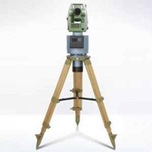
The analytical fast north finding is mainly composed of inertial sensor components, horizontal turntable, base (including shock absorber), control circuit and computer. The inertial sensor component is mainly composed of a flexible gyroscope and an accelerometer meter, which is used to sense the angular velocity of the earth’s rotation and the acceleration of gravity.

2. Decomposition of the angular velocity of the earth’s rotation

The earth’s rotation angular velocity (15.0411 degrees/h, 7.29213101e-5rad/s) vector is parallel to the earth’s axis, and the north direction is positive. At any point P on the earth’s surface, the rotation angular velocity at that point can be decomposed into a vertical component and a horizontal component, which is the latitude value of point P. The true north position refers to the direction of the horizontal component of the earth’s rotation angular velocity.

3. The principle of gyro north finding in the horizontal state of the platform

The selected flexible gyro for north-seeking azimuth vertical reference is a dual-axis rate gyro, which has two orthogonal input X, Y and two corresponding output shafts, and the rotor axis is the Z axis. Ericco’s MEMS gyroscope ER-MG2-100 is used for north finding, and the built-in IMU is used for inclination measurement and azimuth calculation.  In order to eliminate the influence of the vertical component, it is always desired that the XY axis of the gyro is in the horizontal plane (or as close as possible to the horizontal state). At this time, the horizontal component of the ground speed sensitive to the two axes is related to the north-seeking angle.

Theodolite is a measuring instrument designed to measure horizontal and vertical angles based on the principle of angle measurement. Its function is to accurately measure the horizontal and vertical angles of the measuring object. It is mostly used in many fields such as construction, road and bridge construction. Ericco’s Economical MEMS North Finder ER-MNS-04 (0.5°/1°) is composed of MEMS gyroscope, accelerometer, mechanical rotation device and signal calculation circuit. The product collects the output of the gyroscope at different azimuth angles and performs. The signal processing calculates the azimuth angle of the device.

Founded in 2006, Ericco is an industry leader with rich product experience in the field of FOG North Seeker & MEMS North Seeker mining north finder

If you want to learn more about north finder, you can log in https://www.ericcointernational.com/ for more details.

north-seeking meaning

north seeking gyro

how do north seeking gyro work

gyro survey tool

gyro tool drilling

FOG North Seeker

MEMS North Seeker

Land Positioning and Orientation System

mining north finder

mining north seeker

GWD – Gyro-while-drilling Technology Superior to Traditional MWD


The accuracy of wellbore trajectory positioning is critical to the success of offshore drilling operations, especially in environments with a high risk of wellbore collisions. The use of gyroscopic technology to implement drilling operations can reduce this risk, and gyroscopic measurement technology can improve measurement accuracy, reduce the risk of wellbore collision, and improve the spacing factor between wells.

Over the past decade, the need to minimize non-productive time and make drilling operations more efficient has prompted a wave of new technology releases aimed at drastically reducing the days-to-depth curve. Through continuous innovation, the average time to drill a well has been shortened significantly, resulting in significant technical achievements.

Compared to magnetic surveying MWD (measurement-while-drilling) tools, gyroscopic measurement technology is considered to be a better choice because it can provide more accurate measurement data without worrying about magnetic interference. As oil and gas well designs become more complex, GWD (Gyroscopic Measurement While Drilling) systems continue to expand the use of this technology, enabling real-time measurement data collection while drilling. In addition, the pioneering of solid-state gyroscope technology has led to the introduction of new systems that are stronger, more durable, and more accurate in measurement than previous products.

Offshore oil and gas drilling, because most of them drill multiple wells on one drilling platform, also known as batch drilling, collisions between wells are easy to occur. Once a collision occurs, it may lead to catastrophic HSE (health, safety and environmental protection) incidents. Therefore, continuous innovation and support of measurement technology is required.

Gyro Technology

GWD technology collects real-time measurement data, which enables more accurate wellbore positioning and safer drilling operations. The GWD system can be used with the most commonly used MWD tools and does not require the use of wired gyroscopes to orient or steer the BHA and drill. When accurate wellbore steering is critical for collision avoidance and trajectory positioning, the use of GWD systems to obtain real-time information on wellbore orientation to improve operational performance and safety may be a major factor different from traditional MWD.

The current all-around solid-state gyroscope, powered by a new set of sensors, has two independent three-axis sensor probes. These solid-state sensor probes accurately measure the Earth’s rotation rate and are more robust than conventional designs. The system is immune to mass unbalance errors, requires no post-run calibration, and can collect measurements during order follow-up, reducing unnecessary downtime in oil drilling.

ERICCO’s ER-MG2-100 and ER-MG2-022 can be used in GWD to provide real-time azimuth, inclination and tool face measurement data, while the bias instability of ER-MG2-100 is 0.02°/h, The ER-MG2-022 is 0.3°/h, which can improve the measurement accuracy, thereby improving the well spacing factor to meet the dual goals of wellbore positioning accuracy and measurement efficiency.

ERICCO, established in 2006, is an industry leader with extensive product experience in the field of GWD gyroscope while drilling technology. If you want to know more related product information, please click on our official website for more details: https://www.ericcointernational.com.

mems gyro manufacturers

fiber optic gyroscope manufacturers

how does a mems gyroscope work

fog gyro

fiber optic gyro price

mems gyro

fiber optic gyroscopes

piezoresistive sensor

fiberoptic gyroscope

fiber optic gyro

Monday, March 21, 2022

Differences between IMU, AHRS, VRU and INS


IMU

Inertial Measurement Unit (Inertial Measurement Unit) is a device that measures the three-axis attitude angle (or angular rate) and acceleration of an object. Generally, an IMU contains three single-axis accelerometers and three single-axis gyroscopes. The accelerometer detects the acceleration signal of the object in the independent three-axis of the carrier coordinate system, and the gyroscope detects the angular velocity signal of the carrier relative to the navigation coordinate system. Measures the angular velocity and acceleration of an object in three-dimensional space. For example, ERICCO’s MEMS IMU ER-MIMU-06, an IMU is installed with gyroscopes and accelerometers on orthogonal three axes, with a total of 6 degrees of freedom, to measure the angular velocity and acceleration of objects in three-dimensional space, which is well known to us “6-axis IMU”. Alternatively, the IMU can add a magnetometer to the accelerometer and gyroscope to form a “9-axis IMU”.

AHRS

AHRS (Attitude and Heading Reference System) is an attitude reference system built on the basis of a 9-axis sensor IMU with a magnetometer added. Because the heading angle has the reference of the geomagnetic field, it will not drift, but the geomagnetic field is very weak and is often disturbed by surrounding objects with a magnetic field. The more orthogonal the magnetic field and the gravitational field, the better the attitude measurement effect, that is to say, if the magnetic field and the gravitational field are parallel, such as the geomagnetic north and south poles, the AHRS cannot be used.

VRU

VRU stands for Vertical Reference Unit, vertical reference unit (vertical gyro). The hardware structure is the same as the IMU. Using the Kalman filter algorithm, based on the output data of the IMU, the output of the pitch and roll angles is added. Some VRUs also output the relative azimuth angle, also known as the Euler angle output. The performance that a VRU can achieve is very dependent on the algorithmic capabilities of the engineer.

GNSS

Global Navigation Satellite System, including GPS (USA), GLONASS (GLONASS in Russia), Beidou Satellite Navigation System (BDS)

INS

The full name of the Inertial Navigation System is the inertial navigation system. The IMU is a device for measuring angular velocity and acceleration, and the INS is to determine the movement of the moving carrier in the inertial reference coordinates through the measured angular velocity and acceleration values.


Friday, March 18, 2022

Application of Fiber Optic Gyroscope North Finder


The north finder is a kind of compass, which is used to find the true north direction value of a certain location. Gyro north finder, also known as gyro compass, is an inertial measurement system that uses the principle of gyro to determine the projection direction of the earth’s rotation rate on the local horizontal plane (ie true north). Its north-seeking process requires no external reference.

In addition to being restricted by high latitudes, its north-seeking measurement is not affected by weather, day and night time, geomagnetic field, and site visibility conditions. The gyro north finder is a kind of precision inertial measurement instrument, usually used to provide azimuth reference for artillery, surface-to-surface missiles and ground radars and other mobile weapon systems. Such as Ericco’s ER-FNS-02 High Precision FOG North Seeker (0.02°-0.1°) is mainly used in static initial alignment of missile launch, weapon targeting and direction control of radar, antenna and armored vehicle, also can be used for coal mining, oil drilling, tunnel construction and geodesy.

According to the type of gyroscope used, the gyroscope north finder can be divided into the following three types:

◆ A north finder with a two-degree-of-freedom gyroscope as the earth’s rotation sensor (such as a suspended pendulum gyro north finder)

◆ North finder using single-axis rate gyro as a sensor (such as strap-down gyro north finder)

◆ Platform North Seeking System

The gyro north finder is extremely sensitive to environmental vibration interference (especially low-frequency vibration interference). According to the usage environment, gyro north finder can be divided into three types: ground-mounted high-precision north finder, vehicle-mounted gyro north finder and ship moving base gyro north finder.

Ground-mounted north finder: Ericco’s ER-FNS-03 FOG gyro North Finder adopts closed-loop fiber optic gyroscope as the core component. It can provide the carrier with true north azimuth angle. It’s widely used in coal mining, oil drilling, tunnel construction and geodesy.

Vehicle-mounted gyro north finder: Ericco’s ER-FNS-01 High Performance Dynamic FOG North Seeker (0.02°-0.5°) consists of high precision, rugged solid FOG, quartz accelerometer, data acquisition and processing unit. It can provide its true north position information when the carrier moves. At the same time, the information of motion attitude, velocity and position of the carrier can also be displayed.

The fiber optic gyroscope north finder is a high-precision inertial instrument that autonomously indicates the azimuth. It can give the angle between the carrier and the true north direction without inputting the latitude value. Using the earth rotation angular rate measured by the fiber optic gyroscope and the angle between the gyroscope and the horizontal plane measured by the accelerometer, the angle between the carrier’s baseline and the true north direction can be obtained through computer calculation. The accelerometer placed on the baseline can be Measure the attitude angle of the north finder.

The fiber optic gyroscope used in the fiber optic gyroscope north finder is a solid-state device with no rotating part, so it can withstand shock and vibration. This is something that other non-optical gyroscopes cannot do.

What is the working principle of the fiber optic gyroscope? Fiber Optic Gyroscope (FOG) is a new all-solid-state gyroscope based on the Sagnac effect. It is an inertial measurement element without mechanical rotating parts. It has the advantages of impact resistance, high sensitivity, long life, low power consumption, and reliable integration. It is an ideal inertial device in the new generation of strapdown inertial navigation system.

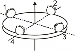
In north-seeking applications based on fiber optic gyroscopes, most of the methods used are FOG rotation at a fixed angle, and the angle of the relative north direction is calculated by determining the offset. In order to accurately point north, the drift of FOG must also be eliminated. Generally, a rotating platform is used as shown in Figure 1. The fiber optic gyroscope is placed on a moving base, the plane of the moving base is parallel to the horizontal plane, and the sensitive axis of the fiber optic gyroscope is parallel to the plane of the moving base. When starting to find north, the gyro is in position 1, and the sensitive axis of the gyro is parallel to the carrier. It is assumed that the angle between the initial direction of the sensitive axis of the fiber optic gyroscope and the true north direction is α. The output value of the gyro at position 1 is ω1; then the base is rotated 90°, and the output value of the gyro is measured at position 2 ω2. Turn it by 90° twice in turn and turn to positions 3 and 4 respectively to obtain angular velocities ω3 and ω4.

The heading angle can be calculated through ω1, ω2, ω3, and ω4. This method can eliminate the zero deviation of the gyro, and there is no need to know the latitude value of the measurement location. If the latitude of the measurement location is a known value, the heading angle can be obtained by measuring only two positions 1 and 3 (or 2 and 4).

North Seeker

north seeking system

north finder wikipedia

north alignment system

northfinder backpack

fibre-optic gyroscope price

interferometric fiber-optic gyroscope

fiber optic gyroscope market

fiberoptic gyroscope pdf

fiber optic gyroscope tarkov

RTK signal is easily blocked? IMU makes RTK have unlimited possibilities

When you use an RTK surveying instrument to measure in some places with obstructions or requiring a large tilt, do you always encounter weak...