Friday, December 29, 2023

Function and Test Analysis of Tilt Sensor Detection System


 At present, tilt sensors are widely used in construction machinery, road machinery, port machinery, lifting machinery and other construction machinery fields, which can realize real-time monitoring and control of angle-related state and attitude in the operation process of construction machinery. However, the inclinometer sensor often has defects such as nonlinear error and temperature drift error in practical application, so that the accuracy is easily affected and the measurement error is too large, which can not meet the requirements of practical application of construction machinery equipment. In addition, in the mass production process of the tilt gauge, it is easy to have the acceleration sensor installed tilt, so that the measurement angle is offset. Therefore, in order to improve the measurement accuracy of the inclinometer sensor, the product needs to be calibrated, temperature drift compensation and accuracy detection before leaving the factory to ensure that the product meets the factory standard.

1.Inclination sensordetection system

The high-precision inclinometer sensor detection system CAN intelligently control the temperature change of the thermostat, the position rotation of the servo motor and the CAN communication control with the tilt gauge. The test data can be displayed and controlled in real time through the interface designed by Labview software. The angle sensor can automate 0° angle calibration, temperature scale aging, angle linear calibration and angle error detection.

2.Inclinometer sensordetection system function

2.1 0° angle calibration function

The tilt measurement sensor detection system uses smooth marble as the cornerstone, which is not easy to shake or deform, and the plane is adjusted to the standard 0° plane by the measuring instrument. When the tilt gauge is located at 0° water level, the system controller SYMC sends 0° calibration instructions to correct the original 0° data.

2.2 Temperature bleaching aging function

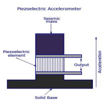
The purpose of temperature drift aging test is to solve the problem that the performance of tilt sensor components is unstable with temperature changes. The specific reason is that the output of tilt sensor and speed sensor is PWM signal, and the waveform is shown in Figure 1.

Figure 1 PMW signal of acceleration sensor

The formula for calculating the output acceleration of the inclination sensor is a = (T1 /T2-0g output)/sensitivity

The output angle of tilt gauge is calculated by θ=sin-1 (a).

In the formula, 0g output and sensitivity are constants in theory, but in fact, they will change due to temperature changes in component performance. To realize temperature drift compensation correction for 0g output and sensitivity values of the tilt measurement sensor, the detection system needs to sample at least 3 typical temperature points (such as -30 ℃, 25 ℃, 60 ℃) under 0g output values and sensitivity values. The output values of the acceleration sensor at 0°, 90°, 180° and 270° were collected at each temperature point, and the output values of the acceleration sensor at other temperatures and positions were linearly corrected by piecewise linear compensation method, so as to calculate the 0g output and sensitivity values of the tilt gauge at different temperatures.

2.3 Angular linear calibration function

The inclinometer sensor adopts linear fitting linearization measures to make the input and output signals have a linear relationship. The specific algorithm adopts two-stage quantization method, such as: take 24° and 26°, and use a straight line connection to replace the original curve; 26 degrees and 28 degrees are also connected by a straight line. The piecewise linear fitting method is adopted for the whole 360°, so that the relationship between the measured data and the actual angle is close to linear relationship. In the algorithm, the more test angle points collected, the more the curve calculated by the algorithm approximates the linear relationship. The inclinometer sensor detection system can randomly select 120 angle sample points, start from 0° angle, every 3° interval, respectively, to carry out piecewise linear fitting of the tested inclination sensor, angle calibration, and maximize the nonlinear error of the inclination sensor.

2.4 Angle detection function

The angle detection system can compare the angle value measured by the inclination sensor with the corresponding angle value detected by the encoder in the detection system, so as to calculate the measurement error of each angle position of the tilt gauge. angle detection selects 60 test sample points, and the selected angle is between the selected point of calibration angle, so as to effectively detect the accuracy of linear fitting algorithm of tilt measurement sensor. The angle resolution of the inclinometer sensor product is ±0.1°, and the accuracy of the angle encoder selected by the detection system is ±0.003°, which can make the detection error resolution reach the thousandth grade, effectively ensuring the accuracy of the system angle detection.

3.Check system test requirements

The requirements of the high-precision inclination sensor detection system in the test: ① The ambient temperature in the thermostatic box should be constant, and the change is less than 0.5 ℃; ② Ensure that the positioning of the structure shaft is consistent with the position of the sensor on the turntable, and the deviation of the angle position of 0°, 90°, 180°, 270° is less than 0.1°; ③ Ensure that the turntable will not shake when rotating, and the sensor can be firmly installed on the turntable; ④ Ensure that the support components can be adjusted in height and match the size of the thermostat; The whole device should have sufficient stiffness and will not be deformed in high and low temperature environments.

4.Check the system test results

The high precision tilt sensor detection system can test 96 board tilt sensors at a time, and the entire test cycle is 6 hours. After the 0° calibration is completed, the system conducts temperature drift aging test. Figure 2 shows the temperature drift effect data of the single-board tilt sensor at 180.5° from -30 ℃ to 80 ℃. It can be seen that the temperature drift compensation front and rear tilt sensor has obvious temperature drift performance effects.

Figure 2 Data Curve of Temperature Coefficient

After the temperature bleaching, the system calibrates 120 test angles of the inclination sensor, and the angular resolution of the inclination sensor is ±0.1°. After the calibration of the inclinometer sensor is correct, the detection system randomly selects 60 angles within 360° (which do not coincide with the angle selected by the calibration), and calculates the measurement angle of the tilt measurement sensor and the feedback angle error of the system encoder. The angle error curve formed by the deviation between the measurement angle of the inclination sensor and the feedback angle of the system encoder is shown in Figure 3.

Figure 3 Error curve of angles

After the test is completed, it can be identified from the figure that the angle error of the white curve is greater than -0.3°, which is a unqualified product and needs to be returned to the factory for processing.

Conclusion: The measurement accuracy of tilt sensor can be greatly improved by calibrating, temperature drift compensation and accuracy detection. Ericco’s ER-TS-3160VO (accuracy 0.01°) and ER-TS-12200-Modbus (0.001°) have been calibrated at 0° angle, temperature drift aging function test, angle linear calibration and angle detection before leaving the factory, so their accuracy is not easily affected, resulting in excessive measurement errors.

The application of high precision inclination sensor detection system realizes intelligent testing instead of manual testing. Production practice has proved that the test cycle of the tilt gauge is reduced from the original 9 h to 6 h, and the unmanned test can still be carried out at night, to achieve two batches of test a day, and the number of test pieces per cycle is increased from the original 60 pieces to 96 pieces, which greatly saves labor costs and improves production efficiency and product quality.

Calibration Method of Accelerometer

 Accelerometer is a kind of equipment used to measure the acceleration of objects, in order to ensure the accuracy of the data in the process of vibration and shock test and measurement, according to the frequency of use and the use of environmental conditions to determine the calibration cycle, usually half a year or one year. In some critical tests or costly destructive tests, calibration is recommended before each use. This article will introduce the calibration method and use skills of accelerometers.

1.Calibration method

The calibration of the accelerometer is the key to ensure the accuracy of its measurement results. Here are some common calibration methods:

1.1 Static Calibration

Static calibration is a calibration performed in a stationary state. Place the accelerometer on a horizontal table and record its output value. Its zero drift and sensitivity can be determined by comparing it with known gravitational acceleration values.

1.2 Dynamic Calibration

Dynamic calibration is carried out when the object is moving in a straight line at uniform speed. Fix the meter on the object and record its output value during movement. The deviation can be determined by calculating the difference between its output value and the expected acceleration during movement.

1.3 Comparison Calibration

Comparative calibration is the calibration of an accelerometer by comparing it with a reference addition known to be of high accuracy. Place both of them on the same object, perform the same motion, and record their output value. By comparing the difference between the two, the error to be calibrated can be determined.

2.Using ways

Reasonable using ways can improve the measurement and analysis of the accelerometer, the following are some commonly used techniques.

2.1 Fixed Position

In the acceleration measurement, the accelerometers should be fixed on the measured object as far as possible, and ensure that its position is stable to avoid interference with the measurement result due to movement or vibration.

2.2 Increasing the sampling rate

The resolution and sensitivity of the accelerometer can be improved by increasing the sampling rate appropriately. When measuring rapid acceleration and deceleration, a higher sampling rate allows instantaneous changes to be more accurately captured.

2.3 Filter Processing

The output signal may contain noise or high-frequency vibration components, which can be filtered to reduce noise and extract useful signals. The commonly used filtering methods include low-pass filtering and high-pass filtering.

3.Calibration precautions

3.1 Installing of the Sensor

Different installation methods will significantly affect the resonant frequency of the sensor, that is, the high-frequency response of the sensor. The following figure illustrates the effect of the installation method on the resonant frequency. Screw installation is preferred, followed by hot melt adhesive or quick-drying adhesive, then double-sided adhesive and so on.

3.2 Selection of sensor cable

Calibrate the sensor cable as far as possible to choose a relatively soft cable, such as silicone or PVC cable, which can reduce the impact of the cable on the sensor, including the shaking table moving core. During the actual test, it is recommended that the cable and sensor be fixed on the same structure. Due to the limited mounting surface during the sensor calibration process, it is recommended to use a flexible cable connection.

3.3 Calibration of X axis of three-axis sensor

The X axis of most three-axis sensors is inverted, so the frequency response of the sensor X axis is usually narrower than the frequency response of the Y and Z axes. Moreover, when testing the X-axis, the top line is out, and attention needs to be paid to the fixing of the cable.

In summary:

Through the above content, you can understand the calibration method of the accelerometer, the use of skills and precautions. Ericco’s ER-QA-03A and ER-QA-01A can be calibrated using the above methods to ensure their accuracy and reliability, but also to improve the accuracy of the test and analysis.

The full text link:https://www.ericcointernational.com/application/calibration-method-of-accelerometer.html

Email : info@ericcointernational.com

Whats app:1399288487

Thursday, December 28, 2023

How the Inertial Measurement Unit Works?


How the Inertial Measurement Unit Works

Inertial Measurement Unit (IMU) A device used to measure speed, direction, and gravity. Early on, IMU consisted of two sensors, accelerometer and gyroscope. Accelerometers measure inertial acceleration, while gyroscopes measure angular rotation. These sensors have three degrees of freedom and can measure from three axes. Later, IMUs introduced magnetometers, which measured the direction of magnetic forces and helped improve gyroscope readings. IMU applications include various fields such as tracking, navigation and robotics. IMU helps us determine the instantaneous position, speed, orientation and direction of movement of an object or vehicle.

1.IMU type

1.1 IMU with two sensors — This type of IMU consists of accelerometer and gyroscope. Each sensor has two or three degrees of freedom defined for the x, y, and z axes, and two sensors combined add four or six degrees of freedom. The acceleration values measured by the accelerometer and the angular velocity measured by the gyroscope are recorded separately, while the angles measured using both sensors are calibrated to obtain accurate data. If such an IMU is present around the sensor, it will not be disturbed by external magnetic fields. Its accuracy suffers due to sensor noise and gyroscope drift issues. ·

1.2 IMU with three sensors — This type of IMU consists of accelerometer, gyroscope and magnetometer. All sensors have 3 degrees of freedom, corresponding to 3 different axes, for a total of 9 degrees of freedom. The magnetometer measures yaw rotation (that is, rotation about the vertical axis) and is calibrated against gyroscope data to account for drift. It is mainly used for dynamic orientation calculation when the drift error is small. If the IMU is present inside a magnetic field, its measurements may be affected because it uses a magnetometer.

2.IMU working guidelines

2.1 Accelerometer

There are many types of accelerometers, and mechanical accelerometers and piezoelectric accelerometers are commonly used in IMU technology. Mechanical accelerometers consist of a spring-suspended mass. Measures the displacement of the mass, providing a signal proportional to the force F acting on the mass along the input axis. Calculate the acceleration acting on the device using Newton’s second law, F = ma.

Piezoelectric accelerometers work on the principle of the piezoelectric effect, which is the ability of a material to become electrically polarized when subjected to mechanical stress. PE accelerometers use a PE element with a load mass (seismic mass) attached to form a 1 DOF mass spring system. The system makes one for each direction (left and right, front and back, and up and down in a three-axis accelerometer). Transient changes in stress on the PE element produce a charge at the output terminals of the accelerometer that is proportional to the applied acceleration.

2.2 Gyroscope

Likewise, gyroscopes are also available in different types, but MEMS based gyroscopes (MEMS) are implemented in IMUs. MEMS (microelectromechanical systems) is a technology that uses micromachining technology to create miniaturized mechanical and electrical devices and structures, with sizes ranging from less than one micron to several millimeters.

Gyroscopes use the Coriolis effect, which states that in a reference frame rotating at angular velocity w, a mass m moving with velocity v experiences a force Fc = −2m(w× v). MEMS gyroscopes contain vibrating elements such as vibrating wheels and tuning fork gyroscopes to measure the Coriolis effect. The simplest geometry consists of a single mass driven at a specific speed to vibrate along the drive axis, and when an external angular rotation (secondary rotation) is applied, secondary vibrations are induced along the vertical axis due to the Coriolis force. The angular velocity can be calculated by measuring this secondary rotation.

2.3 Magnetometer

About 90% of magnetometers work using the Hall effect. The principle of the Hall effect states that when a current-carrying conductor is placed in a magnetic field, a voltage will be generated perpendicular to the direction of the magnetic field and the direction of the current.

When a constant current flows through a piece of semiconductor material, in the absence of a magnetic field, there is no potential difference at the output. However, when a vertical magnetic field is present, the direction of the current flow is disturbed, creating a potential difference between the output terminals. This voltage is called Hall voltage. Keeping the input current constant, measure the magnetic field strength proportional to the Hall voltage.

3.How to calibrate IMU during operation

IMUs combine input data from multiple different sensors to accurately measure motion. To obtain accurate values, the sensor must be calibrated rather than using raw data. Calibration parameters can be stored in the IMU’s memory and automatically reflected in the result data. Calibration can also be accomplished by using a magnetometer, which reduces directional drift (errors that accumulate over time). Some devices use proprietary sensor fusion algorithms to combine magnetometer and gyroscope data to determine the device’s orientation relative to a global reference frame. Sensor fusion is the process of using signals from two or more types of sensors to update or maintain the state of a system (direction, velocity, and displacement). Sensor fusion algorithms maintain this state using IMU accelerometer and gyroscope signals as well as signals from other sensors (such as magnetometers) or sensor systems. The most popular technique for performing sensor fusion is the Kalman filter.

The Kalman filter is an optimization algorithm for estimating the state of systems with noise and uncertainty. This filter accepts noisy imprecise measurements and it is able to estimate the current state and even predict future states with good accuracy. The Kalman filter uses all sensor axis contributions within the IMU to estimate the direction angle, thereby minimizing drift.

4 .Conclusion

In application fields, IMU is used in various tracking systems such as unmanned navigation systems, vibration control, and measurement. In unmanned navigation systems (drone, aircraft), the navigation-level IMU developed by ERICCO can independently seek north, such as ER-MIMU01 and ER-MIMU-05. Their advantages are: light weight, small size, low Cost, high performance, due to these characteristics they can be mass produced, and equipped with X, Y, Z three-axis precision gyroscope, X, Y, Z three-axis accelerometer, high resolution, can output X, Y, The original hexadecimal complement data of Z three-axis gyroscope and accelerometer (including gyroscope hexadecimal complement value temperature, angle, accelerometer hexadecimal temperature, acceleration hexadecimal complement value); It can also output floating-point dimensionless values of gyroscopes and accelerometers processed by low-level calculations. The angular velocity random walk in the gyroscope is less than 0.005, the paranoid stability is less than 0.01, and the accuracy is higher than that of other inertial navigation companies.

If you want to learn about or purchase an IMU, please contact our relevant personnel.

contact me:

website:https://www.ericcointernational.com/inertial-measurement-units

Email: info@ericcointernational.com
WhatsApp: +8613992884879

What are the Advantages of Tilt Sensor


The tilt sensor is a very accurate measuring tool for small angles. It can measure the inclination of the measured plane relative to the horizontal position, the parallelism and perpendicularity of the two components. It has become an indispensable and important measuring tool in bridge construction, railway laying, civil engineering, oil drilling, aviation and navigation, industrial automation, intelligent platform, mechanical processing and other fields.

1. The principle of tilt sensor

The working principle of the inclination sensor is based on microelectromechanical system (MEMS) technology and accelerometer principle. It is equipped with tiny accelerometers, and by using gravity, inertia and other mechanical principles, to detect the object’s tilt angle relative to the Earth’s horizontal plane.

When the object is at rest, the tilt sensor is subjected to gravity, which causes the accelerometer to align with the vertical direction of the Earth. When the object tilts, the direction of the accelerometer changes accordingly, resulting in an electrical output indicating the angle and direction of the object’s tilt.

2. Advantages of tilt sensor

The main benefits of tilt sensors include:

2.1 High Precision

The tilt sensor adopts MEMS technology, which has the characteristics of high precision, high stability and low noise, and can realize the high precision measurement and control of the tilt angle of the object. ER-TS-12200-Modbus is a high-precision wireless inclination sensor, its accuracy can reach 0.001°, using industrial MCU, three-proof PCB board, imported cables, wide temperature metal shell and other measures, its industrial design has extremely high measurement accuracy and anti-interference ability. It is suitable for remote real-time monitoring and analysis of industrial sites, dilapidated buildings, ancient buildings, civil engineering, tilt deformation of various towers and other needs.

2.2 Compact and Lightweight 

The tilt sensor is small in size, light in weight, easy to install and carry, and is suitable for various occasions and environments. ER-TS-32600-Modbus its volume is 94*74*64mm, weight is only 460g, very easy to install and carry. Is an ultra-low power consumption, small volume, high-performance wireless inclination sensor, it uses lithium battery power, based on the Internet of Things technology Bluetooth and ZigBee(optional) wireless transmission technology, it meets the needs of users in industrial applications without power supply or real-time dynamic measurement of object attitude angle.

2.3 High Reliability

The tilt sensor has high vibration resistance, impact resistance, water and dust resistance, and can run stably in complex environment for a long time. For example, the ER-TS-3160VO, which has a seismic resistance higher than 20000g, is adopted IP67 protection grade, it has the characteristics of strong shock and vibration resistance, especially suitable for a variety of harsh industrial environments.

Summary: With the continuous development of technology, inclination sensors will have wider prospects and advantages.

1. High precision and stability: With the continuous improvement of measurement accuracy and stability requirements in various fields, the future development direction of inclination sensors will be to improve the accuracy and stability of induction components.

2. Multi-functional: the inclination sensor will gradually develop in the direction of multi-functional, such as integrating the functions of gyroscopes, magnetometers and other sensors to achieve the measurement of a variety of parameters.

3. Intelligent: inclination sensor will be combined with artificial intelligence, internet of things and other technologies to achieve intelligent perception and data processing, improve application efficiency and user experience.

4. Miniaturization: In order to meet the application needs of some special scenarios, the volume of the inclination sensor will gradually shrink and develop in the direction of miniaturization.

5. Wide application: With the continuous progress of inclination sensor technology and the expansion of application scenarios, its application in various fields will be more extensive, bringing more convenience to people’s life and work.

Wednesday, December 27, 2023

How the MEMS Inertial Measurement Unit works?

 The inertial measurement unit is a device that measures the three-axis attitude angle (or angular rate) and acceleration of an object. Generally, an inertial measurement unit contains three single-axis accelerometers and three single-axis gyroscopes. The accelerometer detects the acceleration signals of the object in three independent axes of the carrier coordinate system, while the gyroscope detects the angular velocity signal of the carrier relative to the navigation coordinate system. Measure the angular velocity and acceleration of the object in three-dimensional space, and use this to calculate the attitude of the object. It has very important application value in navigation. IMUs are mostly used in equipment that require motion control, such as cars and robots. It is also used in situations where precise displacement calculations using attitude are required, such as inertial navigation equipment for submarines, aircraft, missiles and spacecraft.

The principle of an inertial measurement unit is very similar to taking small steps in the dark. In the dark, due to the error between your estimate of the step length and the actual distance traveled, as you take more and more steps, the difference between your estimated position and the actual position will become farther and farther. When taking the first step, the estimated position is relatively close to the actual position; but as the number of steps increases, the difference between the estimated position and the actual position becomes larger and larger. This method is extended to three dimensions, which is the principle of the inertial measurement unit.

The academic expression is: Based on Newton’s laws of mechanics, by measuring the acceleration of the carrier in the inertial reference system, integrating it over time, and transforming it into the navigation coordinate system, the velocity in the navigation coordinate system can be obtained. , yaw angle and position information.

Therefore, in layman’s terms, the inertial measurement unit is a strapdown inertial navigation system. The system consists of three acceleration sensors and three angular velocity sensors (gyros). The accelerometer is used to feel the acceleration component relative to the vertical line of the ground. The speed sensor is used to get a feel for the angle information.

It is worth noting that the inertial measurement unit provides relative positioning information. Its function is to measure the movement route of the object relative to the starting point, so it cannot provide information about your specific location. Therefore, it is often combined with GPS. Used together, when the GPS signal is weak in certain places, the IMU can play its role, allowing the car to continue to obtain absolute position information and not get “lost.”

If you want to purchase an IMU please contact us.

concate me:

website:https://www.ericcointernational.com/inertial-measurement-units

Email: info@ericcointernational.com
WhatsApp: +8613992884879


How to Improve the Long-term Stability of the Quartz Accelerometer?


Quartz accelerometer is an inertial navigation device that uses Newton’s second law (Law of inertia) to measure acceleration, and is widely used in aerospace, aviation, navigation, transportation, oil and other fields. Because of its simple structure, small size, high precision and sensitivity, good stability, low power consumption, low cost, it is more widely used in the space field of missiles and launch vehicles. From the perspective of various models, the long-term stability of quartz accelerometers has also become a bottleneck restricting the development of inertial systems. Therefore, this paper will briefly introduce how to improve the long-term stability of quartz accelerometer from the following points.

Factors affecting long-term stability

Influence factors of partial value

It can be seen from the important indexes that affect the stability of the quartz accelerometer that the size of the offset value and the long-term stability play an important role in its accuracy. For example, the bias of ER-QA-03A1 is 3mg, and the bias repeatability is 10μg, which has the attribute characteristics of high precision. According to the main reasons affecting the occurrence of bias, in the current technical state, according to the quartz accelerometer error model, the main reasons affecting the stability of the offset value are the zero change of the differential capacitance sensor (the size drift of the support structure) and the change of the elastic recovery Angle of the pendulum plate beam (the slow release of the processing stress and the structural stress), which cause the direct cause of the offset error.

Scale factor influencing factors

Calculation formula of scale factor K1: K1=P/KT=mL/ BlL

It can be seen from the formula that the stability of the scale factor is determined by the torque coefficient and the pendulum property. Further analysis is determined by the stability of the detection mass m, the working air gap magnetic induction intensity B, the effective length of the coil wire l, the distance from the detection mass center of mass to the pivot L and the distance from the electromagnetic force center to the pivot L. The change of the performance of the pendulum component and the instability of the scale factor of the torquer are the main reasons leading to the change of the accelerometer factor stability, that is, increasing the scale factor stability of the torquer can improve the scale factor stability of the accelerometer.

Concrete measures for long-term stability

Application of new high performance permanent magnets

The role of a permanent magnet is providing the magnetic induction in the formula. Theoretically, as long as the mass, length and magnetic induction intensity do not change, the current value can accurately calibrate the acceleration value. However, in general, the magnetic properties of permanent magnets change with temperature and time. The change of temperature directly determines the accuracy parameters of the accelerometer, and the drift of time directly limits the stability parameters of the accelerometer. Therefore, temperature and time are the two most important factors restricting the application of accelerometers. Under the premise of ensuring the remanent temperature coefficient, the coercive force temperature coefficient is also more than one order of magnitude lower than that of traditional magnets, which can effectively reduce the magnetic field drift caused by the fluctuation of coercive force field, and the magnetic field will show better temperature stability and time stability, which is expected to ensure the long-term stable use of quartz accelerometers in variable temperature environments.

Temperature compensation technique

Temperature is an important aspect that affects the accuracy of quartz accelerometer. The fluctuation of the operating temperature inside the inertial device and the thermal gradient around the shell will cause errors. The thermal expansion and cold contraction of the material will deform the structural parts of the accelerometer and cause interference torque to the accelerometer. Temperature changes will also change the physical parameters of various materials inside the device, and the change of magnetic properties of the torquer will also directly affect the measurement accuracy of the accelerometer, so the accuracy of the accelerometer can be improved through magnetic temperature compensation. At present, the products represented by ER-QA-01A3 have applied this technology to ensure its accuracy in long-term use.

Through the analysis of the factors affecting the long-term stability of the quartz accelerometer, it is realized that its stability is closely related to the energy of the pendulum material and the magnetic field stability of the torquer. The long-term stability is improved by using new high performance permanent magnets and temperature compensation technology.

The full text link:https://www.ericcointernational.com/application/how-to-improve-the-long-term-stability-of-the-quartz-accelerometer.html

Email : info@ericcointernational.com


 Whats app:13992884879


Choose a suitable IMU to make your drone flight more stable and safe

         As one of the core components of drones, IMU plays an irreplaceable role. Its high precision, fast response and freedom from extern...