Wednesday, January 31, 2024

Calibration method and error analysis of low-precision MEMS IMU

 MEMS IMU, Micro Electro-Mechanical System Inertial Measurement Unit, low-precision MEMS IMU is a sensor module that integrates a micro accelerometer and a micro gyroscope. It is mainly used to measure the acceleration and angular velocity changes of objects in three axes. This kind of sensor is mainly used in fields such as attitude angle measurement, motion status monitoring, navigation and positioning. Compared with high-precision MEMS IMU, low-precision MEMS IMU has lower accuracy, but has the characteristics of small size, light weight, and low power consumption. It is suitable for application scenarios with low accuracy requirements and limited cost.

The accelerometers of low-precision MEMS IMUs are generally produced using micromachining technology and have the advantages of wide measurement range, high resolution, and good reliability. The gyroscope is implemented using vibration or optical principles, which has the advantages of fast startup speed and high measurement accuracy. In a low-precision MEMS IMU, the accelerometer and gyroscope perform data fusion and combine the initial position and velocity information to calculate the object’s current position and attitude.

In practical applications, low-precision MEMS IMU needs to be used in conjunction with other sensors, such as GPS, barometer, magnetometer, etc., to improve the accuracy and stability of navigation and positioning. At the same time, low-precision MEMS IMU also requires necessary calibration and calibration to reduce the impact of various error sources and improve the accuracy and reliability of measurements.

This article will introduce the calibration process, error sources and analysis of MEMS IMU.

1.Calibration process

The calibration process of low-precision MEMS IMU mainly includes the following steps:

1.1 Static calibration

Static calibration is an important part of the low-precision MEMS IMU calibration method. Its main purpose is to eliminate the offset error of the IMU and improve its measurement accuracy in a static environment. During the static calibration process, the IMU needs to be placed in a static state, raw data in all directions is collected, and the calibration algorithm is used to estimate the parameters of the accelerometer and gyroscope. The static calibration method is relatively simple, but it is necessary to ensure the stability and temperature consistency of the IMU to reduce the impact of the external environment on the calibration results.

                                                                                           IMU calibration

1.2 Dynamic calibration

Dynamic calibration is another important link in the low-precision MEMS IMU calibration method. Its main purpose is to eliminate the sensitivity error and cross-coupling error of the IMU and improve its measurement accuracy in a dynamic environment. During the dynamic calibration process, dynamic excitation needs to be applied to the IMU, raw data in all directions is collected, and the parameters of the accelerometer and gyroscope are estimated using the calibration algorithm. The dynamic calibration method is relatively complex and requires the use of additional excitation equipment and precise control of factors such as frequency, amplitude, and phase of the excitation signal.

1.3 Data collection and processing

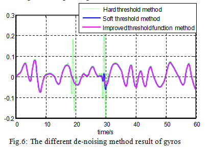
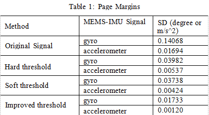
Data acquisition and processing are the basic links in the low-precision MEMS IMU calibration method. Its main task is to collect the original data of the IMU and perform necessary preprocessing and feature extraction. During the data collection process, it is necessary to ensure the accuracy and reliability of the data and avoid interference from electromagnetic interference, noise and other factors. During the data processing process, the original data needs to be filtered, smoothed, denoised, etc. to extract useful feature information to facilitate subsequent parameter estimation and model establishment.

1.4 Error model establishment

Error model establishment is the core link in the low-precision MEMS IMU calibration method. Its main task is to establish an error model based on the collected raw data and known calibration parameters to describe the measurement error of the IMU. In the process of establishing an error model, it is necessary to select appropriate mathematical models and algorithms, consider the impact of various error sources, and use a large amount of data to train and optimize the model. The established error model can be used for subsequent parameter optimization and accuracy verification.

1.5 Parameter optimization

Parameter optimization is a key link in the low-precision MEMS IMU calibration method. Its main task is to continuously optimize the calibration parameters through iteration and reduce the measurement error of the IMU. During the parameter optimization process, it is necessary to select an appropriate optimization algorithm and objective function, and use an error model to guide the optimization process. Optimized parameters usually include accelerometer and gyroscope bias, sensitivity, cross-coupling and other parameters. Through parameter optimization, the measurement accuracy and stability of the IMU can be improved to better meet the needs of practical applications.

1.6 Accuracy Verification

Accuracy verification is a necessary part of the low-precision MEMS IMU calibration method. Its main task is to evaluate the measurement accuracy of the calibrated IMU by comparing actual measurement data with known standard data. During the accuracy verification process, it is necessary to select representative test samples and use the error model to predict and evaluate the test samples. At the same time, the test results need to be compared with the uncalibrated IMU to verify the effectiveness and superiority of the calibration method. The results of accuracy verification can be used as an important basis for evaluating the performance of the calibration method.

1.7 Repeatability Test

Repeatability testing is an important part of the low-precision MEMS IMU calibration method. Its main task is to evaluate the stability and reliability of the IMU performance by conducting repeatability tests at different times and in different environments. During the repeatability test process, it is necessary to maintain the consistency of the test conditions and perform statistical analysis on the test results. By comparing the differences and trends between different test results, the performance and reliability of the IMU under different conditions can be evaluated. At the same time, the results of the repeatability test can also be used as an important basis for evaluating the performance of the calibration method.

2.Error sources and analysis

MEMS IMU errors are of great significance to improving its measurement accuracy and stability. The errors of low-precision MEMS IMU mainly come from bias error, sensitivity error, cross-coupling error, temperature error and repeatability error. The error analysis is as follows

1.Offset error:During long-term use, the accelerometer and gyroscope of MEMS IMU will have offset errors due to factors such as manufacturing processes and materials. Offset errors can cause the IMU to produce measurement errors in its stationary state. In order to reduce the offset error, long-term static calibration is required and the output of the accelerometer and gyroscope are filtered.

2.Sensitivity error:The sensitivity of the MEMS IMU’s accelerometer and gyroscope will be affected by factors such as manufacturing processes and materials, resulting in errors. Sensitivity errors can lead to inaccurate IMU measurements in dynamic environments. In order to reduce the sensitivity error, dynamic calibration is required and the output of the accelerometer and gyroscope are corrected.

3.Cross-coupling error: Cross-coupling error will occur between the accelerometer and gyroscope of the MEMS IMU, especially during high-speed rotation or vibration. Cross-coupling errors can lead to inaccurate IMU measurements in dynamic environments. In order to reduce cross-coupling errors, the physical design and circuit parameters of the IMU need to be optimized, and the outputs of the accelerometer and gyroscope need to be coupled and compensated. 

4.Temperature error: The performance of MEMS IMU is greatly affected by temperature, and temperature drift will cause the measurement accuracy of the IMU to decrease. In order to reduce the temperature error, temperature compensation is required and devices with lower temperature drift are selected. At the same time, materials with good thermal stability can be used in the IMU package to reduce the impact of temperature on the performance of the IMU.

5.Repeatability error:The repeatability error of MEMS IMU refers to the error caused when the same parameter is measured multiple times under the same conditions. Repeatability errors are mainly affected by factors such as manufacturing processes and materials, and can be reduced by improving manufacturing processes and material quality. At the same time, filtering algorithms and statistical methods can be used to smooth the output of the IMU to reduce the impact of random noise and accidental errors.

In short, MEMS IMU error analysis is an important means to improve its measurement accuracy and stability. By analyzing and controlling various error sources, the errors of MEMS IMU can be effectively reduced and its performance improved.

Summarize

The above article describes the calibration method, error sources and error analysis of low-precision MEMS IMU. The output of MEMS IMU will also have deviations, and the calibration coefficients will also have deviations. Therefore, it is necessary to accurately calibrate the error coefficient of the MEMS IMU to improve the calibration accuracy.

As a developer and manufacturer of MEMS IMUs, Ericco has adopted strict control measures for the calibration methods of MEMS IMUs, especially the navigation grade ER-MIMU-01 and ER-MIMU-02 with excellent accuracy and high calibration accuracy. Among them, the gyro accuracy is relatively high, and the bias instability can reach 0.01-0.02°/hr and 0.03-0.05°/hr respectively.

If you are interested in other knowledge about MEMSIMU, please click the link below to learn more.

Tuesday, January 30, 2024

How to Improve Reliability of Tilt Sensors


 1. How to ensure the reliability index of the tilt sensor

For the technical indicators and performance indicators of the tilt sensor, there are usually clear and quantitative index requirements, which can be directly measured and tested when the product leaves the factory. For reliability indicators, it is generally impossible to implement direct measurement and inspection, and it is necessary to carry out reliability design and control of the whole process of product development and production to ensure that the reliability indicators meet the requirements. We mainly discuss the reliability supervision and control, design and evaluation and test of tilt sensor in the development, production and use stage.

2. Reliability design
The development stage of inclinometer sensor can be divided into demonstration stage, scheme stage, development stage and finalize stage. According to the technical requirements of the tilt sensor, the MTBF task value θS of the sensor is determined in the demonstration stage, and the θS is preliminarily demonstrated according to the reliability level of the sensor product.
When the inclinometer sensor is in the project stage, it is necessary to design according to the tactical technical index of the inclination sensor and work out the functional block diagram of the sensor. According to the block diagram of tilt sensor, the internal logic relationship in the block diagram is analyzed, and the reliability block diagram of the newly developed inclination sensor is compiled. According to the reliability block diagram of the inclinometer sensor, the reliability indicators are assigned to each subsystem of the sensor, or the reliability indicators on the technical requirements are weighted, and the results after allocation must meet the reliability indicators of the whole system. After the reliability block diagram is prepared and the reliability index is assigned, the estimated reliability value θP is estimated for the components used in the hardware circuit. According to the obtained θP value, the part of the hardware circuit that affects the reliability of the sensor is designed and changed. At last, the functional block diagram, reliability block diagram, reliability distribution index and reliability predicted results prepared according to the technical requirements of the inclination sensor are reviewed periodically in order to improve the design of the defects that affect the reliability of the sensor. In the reliability design of the tilt sensor, the design needs to be considered as shown in Figure 1.

Reliability design structure of tilt sensor

2.1 Reliability design of hardware circuit
After the inclinometer sensor enters the development stage, the hardware circuit is designed according to the functional block diagram and reliability block diagram.
In the design of hardware circuit reliability, the aspects that need to be considered are shown in Figure 2.

Tilt sensor Hardware circuit reliability design structure diagram

In the process of hardware circuit design, components are the basis of circuit reliability design. In the actual sensor hardware circuit, due to different environments, load changes and a series of reasons such as the design of the sensor drift fault, therefore, in the actual design of the hardware circuit should be integrated into the margin design, after the completion of the hardware circuit design, before the data transmission, it is required to check the integrity of the components in the hardware circuit to ensure that the sensor is powered on. Correct and intact data transmission between each unit. In addition, limit testing and reasonableness testing are performed on all analog and digital inputs and outputs in the hardware circuit.
2.2 Software program reliability design
In the design of the hardware interface software of the sensor, the failure detection of the external input or output device must be considered first, and when the failure is detected, the software can restore the interface to a certain safe state, and the hardware failure mode involved is also required to be considered. When the sensor transmits data, in order to ensure the authenticity and reliability of the data received by the receiver, the data sent by the sender is required to use a specific format and content, so that the sender and the receiver can use the agreed method for verification. In the process of software design, its reliability design structure is shown in Figure 3.

Tilt sensor Software reliability design structure diagram

When the software program of the sensor is written, the first thing to consider is the robustness of the software. In software robustness design: First, the power module of the inclinometer sensor may have intermittent failure at the moment of power supply, so that the inclinometer sensor into a potential unsafe state, in order to avoid this state, it is required that the software safely shut down the sensor when the sensor power supply fails, in addition, the power supply of the inclination sensor may have abnormal fluctuations. Software is also required to handle it; Second, the software design must take into account a self-test when the sensor is powered on, verifying that the sensor system itself is safe and can operate normally, and when necessary, the sensor can carry out periodic self-testing; Third, the inclination sensor needs to work normally in electromagnetic radiation, static interference and other environments, which requires the sensor hardware circuit design to be processed according to the technical requirements, so that the sensor can control the external interference within the specified range, when there is external interference, the software is reset again, so that the sensor can still operate normally. Secondly, it is necessary to carry on the margin design when writing the sensor operation program. While ensuring the storage capacity and data channel transmission capacity of each module of the software, the software margin of the inclination sensor should be planned to ensure that the software margin meets the requirements. According to the specific state of each subsystem during software running, the arrangement of various cycles and working time series of software is determined to ensure that sufficient margin is reserved between software working time series.
Finally, consider the data definition when the sensor program is written. When defining the data in the software operation process, it is necessary to ensure that the defined data must be within a reasonable range, so that the sensor can ensure the size and error of the value within the specified range during the data operation process to ensure the accuracy of the data operation. In addition, reasonableness checks are also carried out at the entrance, exit, and other key locations of the software.
2.3 Structural reliability design
In addition to the protection of the external environmental stress, the electromagnetic compatibility of the inclinometer sensor is mainly optimized in the structure of the sensor. Under modern conditions, electromagnetic interference is everywhere, in this environment to make the sensor normal operation, it is required to optimize the sensor in hardware circuit, overall structure, manufacturing process, etc., in order to reduce the sensitivity of the sensor for interference, so that the external entry and internal leakage of electromagnetic interference can be controlled in a acceptable range.
2.4 Process reliability design
Process reliability design is mainly divided into printed board reliability design, electrical interconnection design and “three defenses” design. The reliability design of the printed circuit board requires the layout of the entire circuit board to be reasonable, and a single functional module or functional circuit is placed on a panel as far as possible, which is more convenient for later troubleshooting and maintenance. The circuit board should be rationally arranged on the circuit board, the circuit at all levels should be arranged and combined according to the distribution of the schematic diagram, the input and output of the sensor should be arranged separately, the analog circuit module and the digital circuit module should be isolated, the layout and wiring should be reasonable as far as possible, and the generation of parasitic coupling electromagnetic interference should be suppressed. When placing electronic components on the circuit printed board, it is required to be as suitable as possible for visual inspection of the entire circuit printed board, to facilitate the inspection of the nominal value of electronic components and fault location. When placing large and heavy components on the circuit printed board, it is necessary to reinforce them to prevent damage to components caused by vibration and impact of the sensor and make the sensor unable to operate normally. The design of electrical interconnection requires the sensor process specification to specify the installation and welding temperature and time of the components, the welding specifications of the inserted components and the operating conditions of the welding operators. The “three defenses” design requires the developer to fully understand the use environment of the sensor, master the characteristics of the sensor use environment and the law of change, analyze the stress conditions of the sensor failure in its use environment, and finally choose the suitable defense for the sensor
Enclosures, materials and sensor manufacturing processes.
3 Summary
By analyzing the reliability of inclinometer sensors in the process of development, production and use, we integrate the reliability design of wireless ER-TS-12200-Modbus and single-axis ER-TS-3160VOER-TS-4150VO and other tilt sensors into the development and production of sensors. Through the reliability information collected by customers during the use of such products, the reliability assessment of the sensor is carried out, and the reliability improvement of the tilt sensor is finally completed. 

MEMS-IMU error calibration compensation method that does not rely on precision turntable

https://www.ericcointernational.com/application/mems-imu-error-calibration-compensation-method-that-does-not-rely-on-precision-turntable.html

Research on MEMS-IMU signal denoising technology

 https://www.ericcointernational.com/application/research-on-mems-imu-signal-denoising-technology.html

High Performance Navigation MEMS IMU

 ER-MIMU-02 (0.05 deg/hr)

1. 3 axis gyroscope & 3-axis accelerometer;
2. High performance and small size;
3. Gyro bias instability: 0.05 deg/hr.

ER-MIMU-02 uses MEMS accelerometer and gyroscope with high quality and reliability, RS422 and external communication, baud rate can be flexibly set between 9600~921600, through the communication protocol to set the user’s required communication baud rate. With X, Y, Z three-axis precision gyro, X, Y, Z three-axis accelerometer with high resolution, can be output by RS422 X, Y, Z three axis of gyroscope and accelerometer’s original hexadecimal complement data (including gyro hexadecimal complement the numerical temperature, angle, the accelerometer hexadecimal temperature, the acceleration hexadecimal complement number); It can also output float dimensionless values of the gyroscope and accelerometer processed by the underlying calculation.

Application areas
Antenna and Line of Sight Stabilization Systems
Integrated Navigation Systems & Inertial Guidance System
Flight Control & Guidance System
Attitude Heading Reference Systems (AHRS)
Stabilization of Antennas, Cameras & Platforms
Aerial and Marine Geo-mapping / Surveying


Monday, January 29, 2024

Tilt sensors are booming


Introduction

ER-TS-3160VO Voltage Single Axis Tilt Meter is an analog voltage single axis tilt sensor. Users only need to collect the sensor voltage value which can calculate the current object tilt angle. The built-in (MEMS) solid pendulum measures the change of static gravity field, which is converted into the change of inclination, and the change is output through the voltage (0~10V, 0.5~4.5V, 0~5V optional).
The product adopts the non-contact measuring principle, which can output the current attitude and inclination angle in real time. The operation is simple, there is no need to look for two faces with relative changes. It has the characteristics of small size and strong shock and vibration resistance, especially suitable for harsh industrial environments.

More details: https://www.ericcointernational.com/tilt-sensor/single-axis-tilt-sensor.html

Features
Single axis tilt monitoring
Full range accuracy 0.01°, resolution 0.001°
Output 0~5V, 0.5~4.5V, 0~10V (optional)
Wide voltage input DC 9~36V
Wide temperature working -40~+85℃
Measuring range: 0~±180° (optional)
High vibration resistance>20000g
IP67 Protection
Can output RS232 at the same time, RS485 optional
Small volume (90*40*27mm) (customizable)

Applications
Railway gauge ruler, gauge instrument
Satellite solar antenna positioning
High altitude working vehicle
Mining machinery, oil logging equipment
Medical equipment
Tripod head levelling  
Hydraulic lifting platform
Inclination monitoring
Angle control of various construction machinery
Inspection of bridges and dams

Thursday, January 25, 2024

Tilt Sensor Automatic Calibration System


Full text: https://www.ericcointernational.com/application/tilt-sensor-automatic-calibration-system.html 

1. Tilt sensor calibration method

Tilt sensor is widely used in the field of engineering measurement, and its measurement accuracy is often related to the evaluation of the deformation of structures, which is of great significance to the construction quality control and safety production management of construction engineering site. The manual two-point calibration method is commonly used to calibrate the inclinometer sensor, which describes the relationship between the output voltage and the Angle through a straight line, and is usually only suitable for the inclination sensor with low accuracy requirements. If the sensor has relatively high accuracy requirements, it is necessary to use a higher precision inclination chip and calibration method. Multi-point calibration is an effective calibration method to improve the accuracy of sensors, but in the case of a large number of fixed points using manual trigger, reading and calculation calibration method, not only low efficiency, and by human factors interference, is not conducive to the large-scale production of sensors. By designing an automatic calibration system for tilt sensor based on programmable electric Angle station, we realize the automatic change of Angle, reading and result output in the calibration process of inclinometer sensor, improve the calibration efficiency and sensor accuracy, and reduce the dependence of the calibration process on the technical level and experience of the operator.

2. Principle of automatic calibration of inclination sensor
The calibration of the sensor means that the measured value of the inclinometer sensor with higher precision is input to the inclination sensor to be calibrated as the standard value, and the feedback value of the sensor to be calibrated is obtained for data fitting processing. The common calibration method only calibrates the inclination sensor by two fixed points, and describes the error Angle relationship of the sensor by a straight line. This method is easy to operate and is suitable for tilt sensors with low precision.
However, if the inclinometer sensor with a measuring range of -15°~+15° collects data every 1°, and the error of each Angle is obtained as shown in Figure 1, it can be found that the error of the sensor is not linear with the Angle when the Y-axis interval is set to 0.01°. Therefore, if the sensor is calibrated by multi-point calibration method, the error of the sensor is not linear with the Angle. The accuracy of the sensor can be further improved by fitting a curve to describe the error characteristics of the sensor.

tilt Sensor error distribution

Therefore, this paper adopts the multi-point calibration method that sets 1 fixed point every 1°, and the third-order fitting method based on the principle of least squares to compensate the sensor error. The error fitting model is as follows:
Δφ = a1x3 + a2 x 2 + a3x + a4 (1)
In the formula, Δφ is the error value of the inclination Angle, x is the acquired value of the sensor to be calibrated, and a1, a2, a3 and a4 are the coefficients of the fitting polynomial.

3.Overall system scheme
The automatic calibration system is composed of three parts: electric Angle station, standard inclination sensor and PC calibration software, as shown in Figure 2.

tilt sensor Composition diagram of automatic calibration system

During calibration, the tilt sensor to be calibrated and the standard value sensor are fixed parallel to the electric Angle platform, the electric Angle platform is connected to the PC calibration software using RS485, and the tilt sensor to be calibrated and the standard value sensor are connected to the PC calibration software through the RS232 of the lora module at the receiving end. The calibration software at the PC end sets the Angle of the fixed point, the calibration software automatically controls the electric Angle station to find the corresponding fixed point, and continuously collects data at each fixed point to analyze whether the Angle data of the tilt sensor and the standard value sensor to be calibrated is stable (the difference between the last 10 sets of data collected does not exceed 0.003°). Record the readings of the tilt sensor and the standard value sensor to be calibrated, and automatically rotate to the next set point until all 31 set points are collected, and the software automatically calculates each parameter of the fitted curve according to the collected data.

4. System testing and analysis
4.1 Functional Testing
In order to verify the function of the automatic calibration system, an inclination sensor with a factory accuracy of 0.1° was placed in the system for calibration. The resulting data are shown in Table 2.

tilt Sensor data before calibration

It can be seen from Table 2 that before calibration, the maximum error of the sensor X axis is -0.037°, and the maximum error of the Y axis is 0.031°. The error fitting curve of the sensor calculated by the calibration software is shown in Figure 6.

tilt sensor-Scatter plot of error curve

4.2 Accuracy Verification
In order to verify the accuracy of the calibrated sensor, the automatically calibrated inclination sensor is sent to a professional measuring institution for measurement. The measurement accuracy is required to be 0.01°, and the measurement data are shown in Table 3.

Measurement data of tilt sensors

The measurement results show that the maximum error of X axis and Y axis is 0.006° and 0.009°, respectively, satisfying the accuracy index of 0.01°. The accuracy of the sensor is improved by one order of magnitude after calibration by the automatic calibration system.
5.Conclusions
We demonstrate the design direction of an automatic calibration system for inclinometer sensor, and carry out the calibration and performance test of the system. During the design and implementation of the automatic calibration system, the following conclusions are obtained:
(1) The automatic calibration system based on the programmable electric Angle station can realize the automatic calibration of the inclinometer sensor, effectively improve the calibration efficiency and save labor costs.
(2) The selection of the resolution of the electric Angle station should fully consider the mechanical structure characteristics of the Angle station. Compared with the resolution of 0.007° and 0.00036°, the resolution of 0.0007° can ensure the calibration accuracy while having higher calibration efficiency. The resolution of the ER-TS-12200-Modbus is 0.0005°, and the resolution of the ER-TS-22800 is 0.0008°, so the ER-TS-22800 can achieve higher calibration efficiency while ensuring calibration accuracy.
(3) The experimental results show that compared with the traditional two-point calibration method, using the multi-point calibration method to calibrate the inclinometer sensor and using the third-order curve to fit the error characteristics of the sensor can effectively improve the accuracy of the inclinometer sensor.  

Application of Improved Wavelet De-noising Method in MEMS-IMU Signals

 https://www.ericcointernational.com/application/application-of-improved-wavelet-de-noising-method-in-mems-imu-signals.html

Application of Improved Wavelet De-noising Method in MEMS-IMU Signals

https://www.ericcointernational.com/application/application-of-improved-wavelet-de-noising-method-in-mems-imu-signals.html


contact me :

Email: info@ericcointernational.com

WhatsApp: +8613992884879


Wednesday, January 24, 2024

Tilt Sensor Automatic Calibration System


Full text: https://www.ericcointernational.com/application/tilt-sensor-automatic-calibration-system.html

1. Tilt sensor calibration method

Tilt sensor is widely used in the field of engineering measurement, and its measurement accuracy is often related to the evaluation of the deformation of structures, which is of great significance to the construction quality control and safety production management of construction engineering site. The manual two-point calibration method is commonly used to calibrate the inclinometer sensor, which describes the relationship between the output voltage and the Angle through a straight line, and is usually only suitable for the inclination sensor with low accuracy requirements. If the sensor has relatively high accuracy requirements, it is necessary to use a higher precision inclination chip and calibration method. Multi-point calibration is an effective calibration method to improve the accuracy of sensors, but in the case of a large number of fixed points using manual trigger, reading and calculation calibration method, not only low efficiency, and by human factors interference, is not conducive to the large-scale production of sensors. By designing an automatic calibration system for tilt sensor based on programmable electric Angle station, we realize the automatic change of Angle, reading and result output in the calibration process of inclinometer sensor, improve the calibration efficiency and sensor accuracy, and reduce the dependence of the calibration process on the technical level and experience of the operator.

Influence analysis of IMU accuracy on spoofing detection algorithm

 https://www.ericcointernational.com/application/influence-analysis-of-imu-accuracy-on-spoofing-detection-algorithm.html


Application of Improved Wavelet De-noising Method in MEMS-IMU Signals

https://www.ericcointernational.com/application/application-of-improved-wavelet-de-noising-method-in-mems-imu-signals.html

Application of High Accuracy North-Seeking MEMS IMU

IMU is an inertial measurement unit. Nowadays, MEMS IMU is widely chosen by consumers due to its advantages such as small size, high efficiency, and low cost. Therefore, the accuracy requirements for MEMS IMU will be relatively high. The main factors that can affect the accuracy of MEMS-IMU include Deterministic errors and random errors. Deterministic errors can be eliminated through calibration techniques; for random errors, Kalman filtering (KF) is usually used. However, KF requires a certain filtering model. The random error of MEMS-IMU is weakly nonlinear, non-stationary, and slowly time-varying, and is easily affected by uncertain factors such as the external environment. In this case, it is difficult to establish an accurate error model. At this time, using KF to deal with random errors will lead to low filtering accuracy and even filtering divergence.

Wavelet transform is a signal analysis method developed in the 1980s. Wavelet analysis is suitable for non-stationary signals, it can analyze local features, and can effectively reduce spike noise in non-stationary white noise. In addition, wavelet analysis does not require the establishment of a random error model, so it is very suitable for noise reduction processing of MEMS-IMU signals. The commonly used method for wavelet denoising is the wavelet threshold method, which can be traditionally divided into hard threshold method and soft threshold method. The hard threshold method can preserve the mutation signal well, but the hard threshold function is discontinuous at the threshold λj, which causes some oscillations when the signal is reconstructed using the estimated wavelet coefficients. The soft threshold method is continuous at the threshold λj, but there is a constant deviation λj between the estimated wavelet coefficients and those of the original signal, which results in blurred edges of the reconstructed signal and affects the accuracy of the reconstructed signal. If the improved threshold function has good continuity at the threshold λj, when the wavelet coefficients tend to infinity, the difference between the estimated wavelet coefficients and the original signal tends to zero. The original signal can be better preserved. However, the coefficient β in the improvement function is uncertain. To handle different signals, a large number of different betas need to be tested to adapt to the current signal, which results in poor flexibility.

In response to the above problems, this paper constructs a new wavelet threshold function without uncertainty coefficient, which makes up for the shortcomings of traditional soft and hard threshold functions and has better flexibility. It also shows that the improved wavelet threshold function can effectively reduce the noise of MEMS-IMU. This article will describe traditional wavelet threshold denoising, improved wavelet threshold function, and experimental results and analysis.

1.Traditional wavelet threshold denoising

The basic idea of wavelet threshold denoising was first proposed by Dohono of Stanford University. The algorithm is simple, requires little calculation, and is especially suitable for Gaussian white noise. The basic idea is as follows. Assume that the time signal sequence is:

The noise signal is decomposed after wavelet transformation, and the wavelet coefficient value of the useful signal is greater than the wavelet coefficient value of the noise signal. Once appropriate thresholds are selected at different scales, wavelet coefficient values smaller than the predetermined threshold are directly reset to zero, while wavelet coefficient values larger than the predetermined threshold are retained or reduced. Then, the processed wavelet coefficient values are used to reconstruct the wavelet signal to suppress the noise. The main step of the wavelet denoising method is the process.

(1)Perform wavelet transform on the noise signal y. The basic formula is:

(2) Perform threshold processing on the wavelet coefficient d. Commonly used threshold functions include hard threshold functions and soft threshold functions. Perform threshold processing on wavelet coefficients. Commonly used threshold functions include hard threshold function and soft threshold function.

The hard threshold function can be described as:

The soft threshold function can be described as:

The function graphs of hard and soft threshold functions are shown in Figure 1 and Figure 2 respectively.

(3)Use the threshold-processed wavelet coefficient d to perform inverse wavelet transformation on the signal according to equation (2) to complete the wavelet reconstruction of the signal and obtain the denoised signal. Although the commonly used threshold function is simple and requires less calculation, it also has its shortcomings. The hard threshold function is discontinuous at A, so oscillations occur when the signal is reconstructed using the processed wavelet coefficients. Although the soft threshold function solves the discontinuity problem in hard threshold, there is always a constant deviation that affects the reconstruction accuracy.

2.Improved wavelet threshold function

In view of the shortcomings of the above soft and hard threshold functions, this paper constructs a new wavelet function. The improved wavelet threshold function can be recorded as:

The improved wavelet function image is shown in Figure 3.

As can be seen from Figure 3, the improved wavelet function is continuous at the threshold, which makes the denoised signal after wavelet reconstruction have better smoothness and can retain the characteristics of the original signal. In addition, there is no uncertainty coefficient in equation (5), which is more flexible for denoising.

The continuity and deviation inconsistencies of the improved wavelet threshold function are proved as follows:

3.Experimental results and analysis

Through the MEMS-IMU measured data experiment, the denoising effect of the improved method on the MEMS-IMU output signal was verified.

The experimental conditions are as follows:

Set the MEMS-IMU to static and the gyroscope constant bias to 0.2. /h, gyroscope random white noise set to 10. /h standard deviation (SD). The accelerometer constant bias is set to 5u 10 to 3 g, and the accelerometer random white noise is set to 10 to 2 g SD. The output frequency is 10 Hz and the experimental time is 60 s.

The raw signals from the gyroscope and accelerometer are shown in Figures 4 and 5. The denoising results of different methods for gyroscopes and accelerometers are shown in Figures 6 and 7.

Statistically rank the SD and denoised signals of the original signal for each method. The results are shown in the table below.

It can be seen from Figure 4 to Figure 7 and Table 1 that for the hard threshold denoising method, the reconstructed signal is easy to oscillate. For the soft threshold denoising method, the reconstructed signal accuracy is not high and the signal is not smooth. The improved wavelet threshold denoising method, the reconstructed signal is smooth, and the SD is smaller than the soft and hard thresholds, which fully demonstrates that the improved method has better denoising effect than the soft and hard thresholds.

Conclusion

The wavelet threshold function constructed in this paper overcomes the oscillation problem of the reconstructed signal caused by the discontinuity of the hard threshold function, and also solves the constant deviation problem of the soft threshold function. The noise in the signal is reduced and random errors in the MEMS-IMU signal can be effectively suppressed. So the company that is better at dealing with the signal error of MEMS IMU is ERICCO INERTIAL SYSTEM. As a company that develops inertial navigation products, ERICCO has independently developed MEMS IMU for many years, which can minimize the signal interference of MEMS IMU and improve the signal quality. Optimized for denoising. For example, ER-MIMU-01 and ER-MIMU-02, the accuracy of the gyroscope and accelerometer is relatively high compared to other companies. These two products are independently developed by ERICCO and are considered hot-selling products. If you want to buy MEMS IMU, please contact us.

Tuesday, January 23, 2024

Application of Tilt Sensor in Vehicle Four-wheel Positioning


Article details: https://www.ericcointernational.com/application/application-of-tilt-sensor-in-vehicle-four-wheel-positioning.html

Tilt sensor in the four-wheel locator

For different four-wheel positioning equipment, the key role is to measure the accuracy of the tilt sensor. Modern cars generally adopt front and rear independent suspension, and the main parameters detected by the four-wheel alignment instrument are wheel camber, kingpin rear angle, kingpin internal angle and front bundle. For the measurement of the above tilt angles, except the front beam angle is generally realized by the rotary disk or the angle sensor, and the other angles are generally adopted by the tilt sensor. The tilt sensor is fixed on the four-wheel alignment mounting plate, and then installed on the wheel of the car through the clamp.

Due to the reason of automobile structure, the tilt measurement of automobile wheel positioning angle is divided into direct measurement and indirect measurement. From the definition of wheel inclination, it can be seen that the measurement of wheel camber can be measured directly by the tilt sensor, while the kingpin internal inclination and kingpin rear inclination are not, because the kingpin is installed on the inside of the wheel, generally can not be measured directly by the tilt sensor. The measurement range of wheel inclination should be about ±15°. In today’s models, the inclination adjustment deviation value is generally about 5′, such as: Shanghai Volkswagen PASSAT B5 front wheel camber value is -0°35′ to ±0°25′, so the sensor measurement resolution should be less than or equal to 5′.

Application of Tilt Sensor in Vehicle Four-wheel Positioning

What is car four-wheel positioning?

From the structure of the car, the car’s steering wheel (front wheel), steering knuckle and front axle installation between the three has a certain relative position, this installation with a certain relative position is called steering wheel positioning, also known as front wheel positioning. Front wheel positioning includes

Kingpin back tilt (angle), kingpin inward tilt (angle), front wheel outward tilt (angle) and front wheel front bundle four contents. For the two rear wheels, there is also a relative position between the installation and the rear axle, called the rear wheel positioning. Rear wheel positioning includes wheel roll out (angle) and one rear wheel front bundle. In this way, the front wheel positioning and the rear wheel positioning are called four-wheel positioning.

When the vehicle leaves the factory, the positioning angle is pre-set according to the design requirements. These positioning angles are used together to ensure the driving comfort and safety of the vehicle. However, because the vehicle is sold and driven for a period of time, these positioning angles will change due to traffic accidents, severe bumps caused by uneven road potholes (especially when driving at high speed suddenly encounter uneven roads), chassis parts wear, chassis parts replacement, tire replacement and other reasons. Once the positioning angle changes due to any reason, it may produce uncomfortable symptoms such as abnormal tire wear, vehicle deviation, reduced safety, increased fuel consumption, accelerated wear of parts, heavy direction, and vehicle drift. Some symptoms make the vehicle very dangerous at high speeds.

Application of Tilt Sensor in Vehicle Four-wheel Positioning1

What is a four-wheel locator?

The purpose of four-wheel positioning maintenance service is to diagnose and treat the above causes of vehicle discomfort by measuring the positioning Angle. Generally, the new car should be four-wheel positioning after 3 months of driving, and every 10,000 kilometers after driving, replacing the tire or shock absorber, and after the collision should be timely four-wheel positioning. The correct positioning of the wheel can ensure that the steering is flexible, the seat is comfortable, the straight line driving is maintained, the life of the tire is extended, and the vibration caused by the road is reduced.

At present, most of the instruments used for wheel positioning detection are “four-wheel positioning instrument”. During the detection, the four-wheel positioning instrument first measures the current four-wheel positioning parameters of the car, and then the computer automatically compares it with the stored value of the corresponding model to calculate the deviation value of the four-wheel positioning of the car, and the maintenance personnel can restore the original state by correcting the prompts of the positioning instrument.

In Summary:

Ericco introduces the ER-TS-4256DI1, a tilt sensor for automotive four-wheel aligners, which has multiple interfaces and can be easily embedded into user systems. It can resist external electromagnetic interference, adapt to the harsh industrial environment for long-term work, is the ideal choice for industrial automation control and platform attitude measurement. The main features are as follows:

Biaxial dip measurement (X and Y) 

Resolution less than 0.01°, accuracy 0.1°

Single PCB board, easy to embed into the user circuit system

Single power supply, digital signal (RS485) output

Built-in temperature sensor (digital SPI output)

Vibration resistance 3500g  

Choose a suitable IMU to make your drone flight more stable and safe

         As one of the core components of drones, IMU plays an irreplaceable role. Its high precision, fast response and freedom from extern...