Monday, October 23, 2023

Classification of North Finder


North finder is a compass, is used to find the north direction at a position value. Gyro north finder, also known as gyrocompass, is an inertial measurement system based on the principle of gyroscope to determine the earth’s rotation rate in the horizontal projection direction of the earth. Its north seeking process does not require external reference. In addition to the high latitude limit, it is not affected by weather, day and night, geomagnetic field and site pass conditions. Gyroscope is a kind of precision inertial measurement instrument, which is used to provide directional reference for artillery, surface-to-surface missile and ground radar and other mobile weapon systems.According to the type of gyro used, gyro finder can be divided into the following three types:

1.A north seeker with two degrees of freedom gyroscope as a earth rotation sensor (such as hanging pendulum gyro    north seeker)

2.A north seeker with a uniaxial rate gyroscope as a sensor (such as a strapdown gyro north finder)

3.Platform north seeking system

Fiber optic gyroscope is a kind of high precision inertial instrument, which can be used to indicate the orientation of the carrier and the true north direction.Use of fiber optic gyroscope measured rate of the earth from the Angle of value and the measured gyroscope and accelerometer horizontal plane Angle, through the computer solution can be obtained in the baseline and the true north direction Angle, placed on the baseline of the accelerometer find north finder attitude Angle can be detected.

For more information, please feel free to contact info@ericcointernational.com

What’s a Tilt Sensor?


Tilt Sensor also known as inclinometer, inclinometer, tilt sensor level and inclination meter, is often used in the measurement of horizontal angle change of the system. The level from the simple bubble level in the past to the present electronic level is the result of the development of automation and electronic measurement technology. As a detection tool, the inclination sensor has become an indispensable important measurement tool in the fields of bridge erection, railway laying, civil engineering, oil drilling, aviation and navigation, industrial automation, intelligent platform, mechanical processing and so on. The electronic level meter is a very accurate measuring tool for small angles. It can be used to measure the inclination of the measured plane relative to the horizontal position, the parallelism and perpendicularity of the two parts.

Inclination sensors can be used to measure the change in inclination relative to a horizontal plane. The theory is based on Newton’s second law, which states that, according to the basic laws of physics, inside a system, velocity cannot be measured, but acceleration can be measured. If the initial velocity is known, the linear velocity can be calculated by integration, and the linear displacement can then be calculated. So it’s really an acceleration sensor that uses the principle of inertia. When the tilt sensor is at rest, that is, there is no acceleration on the side or in the vertical direction, only the acceleration of gravity is acting on it. The angle between the vertical axis of gravity and the sensitive axis of the acceleration sensor is the inclination angle. A general sense of angle sensor is static or quasi-static measurement, once has the external acceleration, then the acceleration measured acceleration which outside acceleration, chip, so the angle of the calculation is not accurate, so, now commonly used way is to increase the mems gyroscope chip, and USES the priority of kalman filtering algorithm. Acceleration 3 axes, gyroscope 3 axes, all products here are also called 6 axis or VG (vertical gyro).

With the development of MEMS technology, inertial sensor components have become one of the most successful and widely used MEMS components in the past few years, and micro accelerometer is an outstanding representative of inertial sensor components. As the most mature inertial sensor applications, MEMS accelerometers now have a very high degree of integration, that is, the sensing system and interface lines are integrated on a chip. The tilt sensor integrates the MCU, MEMS accelerometer, analog-to-digital conversion circuit, and communication unit all on a very small circuit board. Can directly output angle and other oblique data, so that people more convenient to use it. Its characteristic is: silicon micromechanical sensor measurement (MEMS) with horizontal plane as the reference plane of 2 axis tilt change. The output angle is based on the level and the datum can be recalibrated. Data output, interface forms including RS232, RS485 and customizable and other ways.Strong ability to resist external electromagnetic interference.

Difference between single axis and 2 axis tilt sensor

The number of mounted axes of inclination sensors can be classified into single axis and 2 axis types. We often say that the inclination sensor generally refers to a single axis of the inclination sensor, and the single axis refers to the central axis around the instrument when measuring the angle, or a certain direction. The 2 axis inclination sensor is a measurement tool designed for the size of the angle between two directions on the basis of the single axis in combination with the specific practical requirements. Angle sensor can be installed in horizontal and vertical, according to the different installation way, single axis  and 2 axis angle sensor measurement of angle is different also, 2 axis flip and pitching angle can be measured, and the single axis can only be measured when choosing horizontal angle and pitching angle, if single shaft when choosing vertical installation can only measure turn angle, pitching angle not optional. Dual-axis inclinometer has the measurement advantages of single axis inclinometer, and has the measurement effect that single axis inclinometer can’t achieve at the same time, and has a wider measurement range.

By directly measuring the acceleration of the measured object, the 2 axis inclination sensor can obtain the linear velocity of the object through integral operation, and then the displacement of the object can be obtained further. Fundamentally, the inclination sensor is still an inertial sensor, which follows the inertial law of object motion and integral calculation method. 2 axis sensors are designed based on this basic principle, in addition to other measuring principles and measuring methods. The 2 axis inclination sensor shares two sensitive axes, which are X axis and Y axis. When the sensitive axis is perpendicular to the direction of gravity, the output change value caused by each tilt of one degree is larger. When the sensitive axis is at an angle of 45 degrees to the direction of gravity, the change value caused by each time is small. When the two are nearly parallel, each offset hardly causes any change in the output. According to this principle, the 2 axis inclination sensor can measure more types of objects and measure more types of angles, greatly improving the measurement efficiency. The 2 axis inclination sensor can basically fulfill the measurement requirements of the single axis inclination sensor.

In addition, the 2 axis inclination sensor can measure the angle of an irregular-shaped object, which can be determined by the angle difference between the two directions. In addition, multiple measurements of the same object from different directions and angles and then the mean value can be measured to get a more accurate angle, which greatly improves the measurement accuracy. The second point is that the 2 axis tilt sensor can measure both the roll angle and the pitch angle of the object. When the X axis and Y axis are perpendicular to the direction of gravity, the two angles obtained at this time are respectively the roll angle and pitch angle of the measured object. Simultaneity of 2 axis inclination sensor can reduce the error caused by separate measurement, which is the key function of 2 axis inclination sensor. However, the accuracy of the 2 axis inclinometer is not as good as that of the single axis inclinometer, which needs to be improved.

Difference between tilt sensor and gyroscope

Gyroscope is an angular motion detection equipment that uses the moment of momentum of a high-speed rotating body to sensitive the shell relative to the inertial space around one or two axes orthogonal to the rotation axis. Gyroscope varieties are many, according to the use of points, it can be divided into sensing gyroscope and indicating gyroscope. Sensor gyroscope is used as a sensor of horizontal, straight, pitch, course and angular velocity in the automatic control system of flying body motion. Indicator gyroscope is mainly used for indication of flight condition, as the appearance of control and navigation. Gyroscopes are piezoelectric gyroscopes, micro-mechanical gyroscopes, fiber optic gyroscopes and laser gyroscopes, which are all electronic, and they can work with accelerometers, reluctance chips, GPS, to make inertial navigation control system.

Do you know how wide the application fields of MEMS IMU are?

The full name of IMU is inertial measurement unit, so how much do you know about IMU? First of all, we know that imu is composed of three single-axis accelerometers and three single-axis gyroscopes. The accelerometer detects the acceleration signal of the object in three independent axes of the carrier coordinate system. The gyroscope detects the angular velocity signal of the carrier relative to the navigation coordinate system. For After processing these signals, the attitude of the object can be obtained. calculated.

         Secondly, I would like to share with you some areas where MEMS IMU can be applied. Its application areas are quite extensive. I hope it can help you. The following are the areas where imu can be applied:

North seeking in logging tools/gyro tools

Pointing, steering and guiding in advanced mining/drilling equipment

Initial alignment in weapon/UAV launch systems

Direction pointing and tracking in satellite antenna, target tracking system

Guidance and navigation in navigation grade MEMS weapon system

Orientating and positioning in railway train system

Precision platform attitude measuring and controls

Precision attitude, position measuring in navigation grade MEMS IMU/INS

North finding and positioning in land surveying/land mobile mapping system

Petroleum exploration

Bridge, tall building, tower, dam monitoring

Rock and soil monitoring

Mining

More information:

Web: https://www.ericcointernational.com/inertial-measurement-units

Email: ericco741@163.com

Whatsapp: 13630231561

Wechat: 13992884879


Do You Know Excellent Performance of MEMS North Finder ER-MNS-05?

 The data is acquired from the gyroscope and accelerometer in the MEMS north finder ER-MNS-05, which is used to calculate the system parameters.

Ericco always believes that products win with performance. In order to ensure the excellent performance of products, our technical team will conduct many repeated tests during the research and development process.

If you are interested in the north seeker product, you can send message to me or send quote to contact info, https://www.ericcointernational.com/north-finders
Contact us:
Email: info@ericcointernational.com
WeChat: 13992884879
WhatsApp: 13630231561

Vide Player

Sunday, October 22, 2023

The Difference between Tilt Sensor and Gyro Sensor


The tilt sensor senses the angle of inclination deviation, only data feedback but no command feedback.

The gyroscope measures the angular velocity, senses the action variable, and then controls the steering gear to carry out the repair action command.

The tilt sensor uses Newton’s second law as its working principle. According to the law, we know that when the inclination sensor is stationary, because the side of the object and the vertical direction are affected by other forces, only the action of gravity, that is to say, it acts on the all it has on it is the acceleration of gravity. Therefore, the resulting angle between the vertical axis of gravity and the sensitive axis of the acceleration sensor is what we call the inclination angle, which is the angle we seek.

Tilt sensors are divided into three different working principles and are divided into three types. The first type of inclination sensor is the solid pendulum type, the second type of inclination sensor is called the liquid pendulum type, and the last type of inclination sensor is the gas pendulum type. The working principles of these three different types of inclination sensors will be different. Because of their different working principles, they will have different advantages and disadvantages.

No matter which type of tilt sensor it is, it will be substantially different from a gyroscope. Like inclination sensors, no matter which type it is, it measures the inclination angle at rest. Compared with the inclination sensor, the gyroscope measures the inclination in motion, and the measurement result of the inclination in static is not accurate. So when we measure the inclination in our daily life, whether to choose the inclination sensor or the gyroscope, we can choose according to this essential difference. If the inclination is measured at rest, then the inclination sensor must be selected, and the inclination in motion is measured, and of course the gyroscope is selected. The specific differences are summarized as follows:

1.Different definitions

The gyroscope is an angular motion detection device that uses the momentum moment-sensitive shell of a high-speed revolving body relative to the inertial space around one or two axes that are orthogonal to the axis of rotation. There are many varieties of gyroscopes, which can be divided into sensing gyroscopes and indicating gyroscopes according to their usesThe ER-MG2-022 is a single-axis MEMS angular rate sensor (gyroscope) capable of measuring angular velocity up to a maximum of ±100°/s with digital output compliant to SPI slave mode 3 protocol.  Angular rate data is presented as a 24-bit word, intended for north seeking applications.  An advanced, differential sensor design rejects the influence of linear acceleration, enabling the ER-MG2-022 to operate in exceedingly harsh environments where shock and vibration are present.

The sensor gyroscope is used in the automatic control system of the flying body movement, as a horizontal, vertical, pitch, heading and angular velocity sensor. The indicating gyroscope is mainly used for the indication of the flying condition, and is used as a driving and piloting surface.

2.Different functions

The tilt sensor measures the inclination of all stops. Compared with the inclination sensor, the gyroscope measures the inclination angle during the movement, and the measurement result of the inclination angle in the static state is inaccurate. The gyroscope is not a measuring device, but an auxiliary device. Just like the tank barrel, in order to allow the tank to shoot accurately during the trek, a gyroscope is installed to automatically control the viewpoint of the barrel.

3.Different applications

The tilt sensor is often used for the level measurement of the system. From the working principle, it can be divided into three types of inclination sensors: “solid pendulum”, “liquid pendulum” and “gas pendulum”. The inclination sensor can also be used to measure the inclination relative to the horizontal plane. The amount of change.

The gyroscope sensor was originally used on the helicopter model, and it has been widely used in mobile portable devices such as mobile phones. Not only that, the modern gyroscope is an instrument that can accurately determine the orientation of moving objects, so the gyroscope Sensors are essential controls in modern aviation, marine, aerospace and defense industrial applications.

Friday, October 20, 2023

What are the Methods of North Finding?

 Definition of north finding

The definition of north finding is to find true north, not magnetic north, and the north seeking methods mentioned in this article are all described closely around true north.

True north refers to the Earth’s north pole, which is the intersection of 90° north latitude or the meridian. It is also known as true north. It is the direction that passes through a point on the Earth and points toward the Earth’s geographical north pole. The tangent direction of the true meridian passing through a certain point on the earth’s surface becomes the true meridian direction of that point.

The theory of finding north

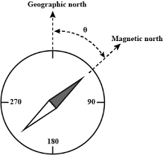
Magnetic north is the north indicated by a compass, primarily because the poles of the Earth’s magnetic field do not coincide with the geographic north and south poles. Therefore, the north indicated by a compass is magnetic north, not true north, and magnetic north changes over time.

North finding uses a gyroscope to measure the component of the earth’s rotation angular velocity combined with the acceleration value, and then calculates the angle with true north to obtain the azimuth angle value.

The methods of north finding

North seeking mainly includes two north seeking methods: static north seeking and dynamic north seeking. The application principles of these two north seeking methods are introduced below.

Principle of static north finding

Static north seeker includes MEMS gyro north seeker and fiber optic gyro north finder.

Principle: The rotation axis of the gyroscope maintains a constant direction relative to the inertial space, while the Earth rotates around the polar axis relative to the inertial space at its rotational angular velocity. If you use the Earth as a reference, you will see that the gyroscope’s axis of rotation rotates relative to the Earth, so the gyroscope can track and measure the angular velocity of the Earth’s rotation.

MEMS gyro north seeker, which has an input axis and a rotation axis. The sensor includes a motor drive structure, a motor signal output from the motor drive structure, a gyroscope, and a sensor rate for the sensor rate signal output from the gyroscope.

Fiber optic gyro north seekers are mainly used to quickly and autonomously determine the true north direction. The Earth’s rotation angular velocity is obtained through high-precision fiber optic gyroscope tracking, and the Earth’s rotation angular velocity signal is decomposed and solved to calculate the angle between the gyroscope’s main axis and the Earth’s true north to provide the carrier with orientation information.

Principles of dynamic north finding

Dynamic north seeking includes fiber optic gyro compass and fiber optic gyro compass (vehicle, ship, airborne)

Principle: Use the strapdown compass effect to find the direction of true north.

The fiber optic gyro compass consists of: three-axis dynamically adjustable gyroscope, three-axis acceleration sensor, data acquisition and processing module, secondary power supply, optocoupler isolated input and output serial port circuit and other related structural parts.

With so many methods available, they are suitable for different circumstances and are not one-size-fits-all. For north seekers used in most fields, inertial measurement device FOG north seekers and MEMS north seekers are relatively advanced in technology.

Comparison of various gyro north seeking systems

By comparing two gyro north-seeking systems, we discovered the similarities and differences between the static north-seeking method and the dynamic north-seeking method.

Common points:

1.They all use the precession and axis fixation of the gyroscope to be sensitive to the earth’s rotation angular speed.

2.The working principle uses the characteristics of the edge of the gyro chamber, that is, the effect of gravity.

Differences:

1.Theoretical differences

The gyroscopic north seeker uses the output of the gyroscope and accelerometer to calculate its azimuth relative to true north to achieve north seeking. Compared with gyro azimuth and gyro compass, it has the advantage of fast north finding speed. However, during the process of north seeking, due to the short start time of the gyro when the gyro north seeker seeks north, there is a gyro drift trend term that is difficult to eliminate, and this term gradually decreases as the gyro starts. The time increases, so the length of time the gyroscope is activated when the north-seeking instrument seeks north has a great influence on its north-seeking accuracy.

2.Differences in application scenarios

Gyrocompasses are mainly used for navigation, such as ships, submarines, UAVs, weapon systems and reconnaissance platforms, providing high-precision azimuth, attitude, navigation and control information. The ER-FGC-2C high-precision gyrocompass has the characteristics of small size, good stability, and high precision, and is fully suitable for navigation in ships, submarines, drones, etc.

Gyro theodolite is mainly used for measurement of large-scale projects such as mines and tunnels. The gyroscope part provides accurate azimuth reference. At the same time, gyro-theodolite can also be used for weapon system aiming.

Gyro-theodolite has high north-finding accuracy, but it cannot be used on mobile carriers such as airplanes and ships because the suspended gyroscope is suspended from the instrument box with a flexible metal belt. On a moving carrier, the instrument shell moves with the carrier. Severe vibrations will cause the flexible metal belt to loosen and fail to maintain a tight state, causing the gyroscope’s movement to lose its original pattern and become unable to work.

3.Differences in performance features (north seeking time and north seeking accuracy)

The north seeking time of the gyro north seeker is short, generally within 5 minutes, and the accuracy can reach about 0.1’. At the same time, there are very few north seekers that can achieve this level of accuracy. ERICCO’s ER-FNS-02 high-precision FOG north seeker has an accuracy of (0.02°-0.1°) and is used for high-precision initial alignment and direction control solutions, which provides a lot of convenience for work. Accuracy can improve relatively over time. The north-finding time of a gyro-theodolite generally takes about 5 to 20 minutes, and the accuracy can reach 10”.

Most recommended north finding equipment

Through the analysis of the two types of north seeking methods, the most suitable north seeking tools for us to use in most fields are MEMS north seekers, FOG north seekers, etc.

The fiber optic gyroscope north seeker uses a closed-loop fiber optic gyroscope as the core component. It is mainly composed of an inertial measurement unit (IMU), a digital signal processing unit and a mechanical part. Provides true north azimuth for the carrier.

The ER-MNS-06 MEMS north seeker is the world’s smallest three-axis MEMS north seeker. It consists of a three-axis MEMS gyroscope and an accelerometer and can measure true north. It has the characteristics of small size, light weight, low power consumption and resistance to harsh mechanical environments, and is widely used in mining, tunnel construction and other fields.

When choosing the most appropriate north-finding device, both gyro-theodolite and gyro-north-finder achieve north-finding on a static basis. Therefore, we can start from the respective characteristics of these two types of devices and complement each other in research or use to achieve coordination of north-seeking accuracy and north-seeking speed.

This article introduces the brief knowledge of the north-finding method. I hope you have a basic and clear understanding of the north-seeking method. If you want to know more about north seeking, you can find useful content in “More Technical Questions”. If you are interested in north finder related products, you can click on “Products in article”. For any questions, please leave your opinions in ‘Ask a Question’ below.

If you need a north seeker, you can send your needs directly to the email . We will send the price and catalog to you!
E-mail:info@ericcointernational.com

Thursday, October 19, 2023

Tilt Sensor Test Bridge Deflection


Tilt sensors measure bridge deflection is applicable to the deflection test of any bridge span length at any position, and belongs to the field of bridge detection technology, in particular, it relates to a high-precision and high-efficiency bridge deflection test method in the process of bridge detection.

Background technique

In bridge testing, it is necessary to measure the deflection of the bridge, and the accuracy of the deflection measurement data is directly related to the assessment of the bridge state. Meanwhile, the timeliness of the bridge testing is required. Therefore, in the process of bridge inspection, the high precision and high efficiency bridge deflection testing system is very important. In the prior art, the field test of bridge deflection generally adopts the following methods: 1.Optical measuring instruments such as level are used to measure bridge deflection. Although the operation is simple, the measurement accuracy is low, and the measurement results are greatly affected by human influence and interference, which cannot be applied to the test of bridge dynamic deflection and the error is large. 2.The use of dial meters, dial meters and other displacement meters to test the bridge deflection, the scaffolding needs to be set up below the beam body, so as to install the deflection test instrument on the scaffold, but in the scaffolding under the bridge, there is a complex process, time-consuming and laborious, and higher scaffolding has a greater safety risk, its own shaking and uneven settlement at the bottom will affect the test results of bridge deflection. 3.The use of photoelectric image principle, through the acquisition of image signals, the use of data processing method, to obtain the deflection value of the bridge, its working principle is complex, image data acquisition is limited by weather, light and other specific conditions, data processing is complex, and the cost is high, the accuracy is low, the actual operability is poor. 4.Based on the principle of connecting pipe, the deflection of bridge is directly measured according to the change of liquid level in the open connecting pipe. This method is simple in principle, but due to the viscous resistance between liquid and pipe wall and the capillary action between water and pipe wall, the test accuracy is not high, and it cannot be applied to the test of dynamic deflection of bridge.

Therefore, the existing bridge deflection testing device has the following defects: 1.Low test accuracy and large error; 2.The test device installation is complicated, the data collection is more complicated, the labor cost is high, the work efficiency is low; 3.It cannot be applied to the detection of dynamic deflection of Bridges and the deflection of bridges across large rivers and grand canyon.

How do inclinometer measure bridge deflection?

Tilt sensor measurement of bridge deflection is a bridge deflection test method based on dip angle, which converts the dip angle change of bridge section into the change of bridge deflection. In other words, the inclinometers is arranged in 5 sections of the bridge to measure the angle of section. The (electrical) signal of the change of dip angle is timely transmitted to the acquisition system through signal cables, and the mathematical relationship formula between bridge deflection and dip angle is calculated by using the dip angle value of section. And then calculate the deflection at any one position.

For example, if we want to measure the deflection of a bridge at any position, we place an ER-TS-4258CU current type biaxial tilt sensor at this position of the bridge, so that the tilt sensor of the 5 sections can be measured, and the signal of the inclinometer change is transmitted to the data acquisition system in real time through the current. We can use the dip value measured by the tilt sensor of the section arrangement to calculate the mathematical relationship between the deflection and the dip angle of the bridge, and then calculate the deflection that needs to be measured at the bridge position.

The disturbance is, in layman’s terms, the amount of deformation. The disturbance of the steel structure such as the cantilever beam should meet the corresponding specifications. The deformation should not be too large, and the formula of the material mechanics can be used for calculation. The deflection of the bridge has a corresponding relationship with the corner angle of the section. The deflection of the bridge can be measured by a double-axis inclination sensor mounted on the bridge. The method uses the structural finite element model to calculate the deflection curve of the unit load acting at different positions. The deflection curve is used as the reference displacement mode, and the true deflection is the linear combination of the reference displacement modes. The combination coefficient is determined by using the minimum inclination test data. The method of two-square fitting effectively reduces the influence of test errors.

Summary: The tilt sensor measure bridge deflection is easy to operate and the test data are accurate, the measurement efficiency is high, and the performance is stable and reliable, and it is not affected by the change of bridge structure form and bridge section. It can solve the problems such as the difficulty of deflection testing and the poor accuracy of measurement data of bridges spanning large rivers and grand canyon.

Choose a suitable IMU to make your drone flight more stable and safe

         As one of the core components of drones, IMU plays an irreplaceable role. Its high precision, fast response and freedom from extern...