Ericcogyro is a leader supplier of Inertial Sensor products North Finder,North seeking system,DTG,FOG,MEMS Gyroscope,Accelerometer,IMU,INS,electronic compass, our inertial sensor are sold worldwide and get the good feedback from our clients .
A drone is an aircraft that does not require human piloting. It is equipped with various sensors and control systems and can perform tasks autonomously. The main role of the IMU is attitude control and flight stability. Based on purpose and design features, drones can be divided into the following three types:
✮Fixed wing drone
✮Multi-rotor drone
✮Vertical take-off and landing and transition drone
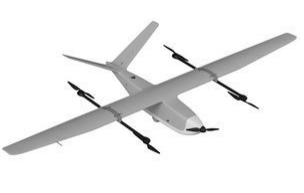
1. Fixed-wing UAV: The design of this UAV is similar to a traditional aircraft, with fixed wings and tail. It is usually used for long-duration flights and wide-area reconnaissance missions, with high speed and the ability to maintain flight stability. For example, the ER-MIMU02 and ER-MIMU06 developed by Ericco can be used in fixed-wing UAVs to perform the initial alignment of the UAV launch system. The machine performs attitude control.
Product advantages: The bias stability of the gyroscope is reduced to 0.5 degrees per hour. This accuracy level has reached that of MEMS sensors. limit value.
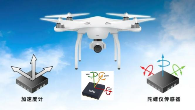
2.Multi-rotor UAV: This type of UAV provides lift and control force through multiple rotors, the most common ones are four-rotor and six-rotor. Multi-rotor drones have vertical take-off and landing and hovering capabilities, and are suitable for tasks such as close-range reconnaissance, aerial photography, and logistics distribution. For example, the ER-MIMU03 and ER-MIMU07 developed by Ericco can be used in multi-rotor drones. These products have built-in acceleration sensors and gyroscopes, which can measure linear acceleration and rotational angular velocity in three directions, and obtain the attitude and speed of the carrier through analysis. and displacement information for precise positioning.
Product advantages: The bias stability of the gyroscope is reduced to 3 degrees per hour. The drone can be well controlled for positioning.
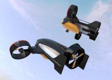
3. Vertical take-off and landing and transition drone: This kind of drone has a variable flight mode and can switch between vertical take-off and landing and horizontal flight. It combines the advantages of fixed-wing UAVs and multi-rotor UAVs, and is suitable for tasks requiring long-term flight and flexible maneuverability. The IMU plays a key role in vertical takeoff and landing and transition drones, and can be used for flight mode conversion. For example, the ER-MIMU04 and ER-MIMU08 developed by Ericco can be used for vertical take-off and landing and transition drones, and can switch flight postures at will.
IMU is not only an important part of the above three types of drones, but also plays an important role in the IMU pod. On the pod, the IMU’s main role is to provide stable images and image transmission. In addition to its two main functions of attitude control and flight stability, it can also be used with other sensors such as GPS (Global Positioning System) and magnetometer to provide more accurate navigation and positioning information.
IMU provides key data for the control and navigation of drones in the field of drone applications, allowing drones to efficiently perform various tasks. Different types of UAVs have different IMU applications depending on their design and purpose, but whether they are fixed-wing, multi-rotor or vertical take-off and landing and transition UAVs, IMU is used to realize their flight control and A key component of navigation.
If you want to learn about or purchase IMU products, please contact us in time.
Tilt sensoris a sensor used to measure the tilt angle of an object relative to the horizontal plane. It can accurately and real-time monitor and record the change of tilt angle, which provides important data support for various industrial applications and scientific research fields.
1. Bridge monitoring
Bridges are an important part of urban traffic, and their stability and safety are crucial to the normal operation of the city. In order to ensure the safety of the bridge, it is necessary to monitor its structure in real time. Tilt sensor can be used to monitor the tilt angle of bridge and provide real-time data support for structural safety. By installing tilt sensors at key parts of the bridge, the tilt angle can be continuously monitored and the data can be transmitted to the control center for analysis. Once abnormal conditions are found, timely measures can be taken for maintenance and reinforcement, thus ensuring the safe use of the bridge. For example, ER-TS-3160VO can be installed in the key part of the bridge to monitor the change of the tilt angle of the bridge, its accuracy is 0.01°, the measurement range is 0~±180°, and the measured value can be output by 0~10V, 0.5~4.5V, 0~5V voltage, which is very suitable for bridge, dam and other monitoring projects.
2. Construction machinery
Excavator — In order to realize the three-dimensional spatial positioning of the excavator, on the basis of installing the angle sensors of each joint of the working device, the platform rotation angle detection device and the platform inclination sensor are installed, and the laser receiver is installed on the bucket rod to detect the height of the horizontal mechanism emitted by the ground laser transmitter relative to the zero position of the receiver. The kinematics model of the excavator is established, and the coordinate transformation matrix of the car body relative to the earth is derived, that is, the car body positioning in three-dimensional space is completed, and the commonly used simple car body elevation positioning formula is obtained, so as to realize the three-dimensional space positioning of the excavator’s excavation trajectory and lay the foundation for realizing the accuracy of the excavator’s three-dimensional space trajectory and the excavator’s depth control.
Other heavy industrial machinery – in addition to excavators, in other heavy industrial machinery, including cranes, lifts, graders, etc., will use tilt sensors, and tilt sensors have a heavy and heavy role in these heavy machinery equipment. It not only ensures that the angle range of these mechanical equipment is within the safety, but also can be raised to the alarm if it is out of range to protect personal safety. For example, the tilt sensor in the retractable robot arm is used to measure the attitude of the cab and the change of the tilt angle of the boom to ensure driving safety. ER-TS-4258CU has strong resistance to external electromagnetic interference and is suitable for long-term work in harsh industrial environments. It can be installed in the retractable arm of the construction machinery, and can measure the attitude of the cab and the tilt angle of the boom in real time, which can ensure the driving safety to the greatest extent.
3. Platform control
Shipborne horizontal platform – The inclination sensor is applied on the shipborne horizontal platform, which is used for shipborne satellite to track the base of the antenna to keep the antenna in a horizontal state at all times, and for real-time control of the platform, which can isolate the pitch and roll motion of the hull and make the platform level.
In addition, the inclination sensor is also applied in the launching process of the ship air bag, and is applied to the hook swing of the large pipe laying ship for monitoring and adjustment.
Application of inclination sensor in automatic levelling system of reference plane of large optoelectronic equipment. The dip angle sensor installed on the base detects the dip angle and direction of the reference plane, converts the angle into the elongation of several mechanical legs according to the leveling algorithm, and drives the elongation of the mechanical legs to make the reference plane level.
Nowadays, with the development of chips, artificial intelligence, and big data technology, drones have begun to become intelligent, terminal, and clustered. A large number of professionals in automation, mechanical electronics, information engineering, microelectronics and other fields have invested in drone research and development. In a few years, drones have flown from military applications far away from people’s sight to ordinary people’s homes. It is undeniable that the development of flight control technology has been the biggest driving force for the transformation of drones in this decade.
Flight control is the abbreviation of flight control system, which can be regarded as the brain of the aircraft. The flight control system is mainly used for flight attitude control and navigation. For flight control, it is necessary to understand the current status of the aircraft, such as three-dimensional position, three-dimensional velocity, three-dimensional acceleration, three-axis angle, three-axis angular velocity, etc. There are 15 states in total. The current flight control system uses an IMU, also called an inertial measurement unit, which consists of a three-axis gyroscope, a three-axis accelerometer, and a three-axis gyroscope. axis geomagnetic sensor and barometer. So what are three-axis gyroscopes, three-axis accelerometers, three-axis geomagnetic sensors, and barometers? What role do they play in an aircraft? What are the three axes?
The three axes of the three-axis gyroscope, three-axis accelerometer, and three-axis geomagnetic sensor refer to the vertical up and down directions of the aircraft’s left and right, front and rear directions, and are generally represented by XYZ. The left and right directions in the aircraft are called roll, the forward and backward directions in the aircraft are called pitch, and the vertical direction is the Z-axis. It’s hard to stand on the ground when the gyroscope isn’t spinning. Only when it rotates does it stand on the ground. This is the gyroscopic effect. Based on the gyroscopic effect, smart people invented the gyroscope. The earliest gyroscopes were high-speed rotating gyroscopes fixed on a frame through three flexible axes. No matter how the outer frame rotates, the high-speed rotating gyroscope in the middle always maintains the same posture. Data such as the rotation angle of the outer frame can be calculated through sensors on three axes.
Due to its higher cost and complex mechanical structure, it has been replaced by electronic gyroscopes. The advantages of electronic gyroscopes are low cost, small size, light weight, only a few grams, and their stability and accuracy are higher than mechanical gyroscopes. At this point you will understand the role of gyroscopes in flight control. It is used to measure the inclination angle of the three XYZ axes.
So what does a three-axis accelerometer do? As mentioned just now, a three-axis gyroscope has three axes: XYZ. Now it goes without saying that a three-axis accelerometer has three axes: XYZ. When we start driving, we feel a push behind us. This thrust is acceleration. Acceleration is the ratio of the change in velocity to the time at which that change occurs. It is a physical quantity that describes the speed of change of an object. Meters to the power per second. For example, when a car comes to a stop, its acceleration is 0. After starting, it takes 10 seconds to go from 0 meters per second to 10 meters per second. This is the acceleration of the car. If the car is traveling at 10 meters per second, its acceleration is 0. Likewise, if it slows down for 10 seconds, from 10 meters per second to 5 meters per second, its acceleration is negative. The three-axis accelerometer is used to measure the acceleration of the XYZ three axes of the aircraft.
When we travel every day, we find our direction based on landmarks or memories. A geomagnetic sensor is a geomagnetic sensor, also known as an electronic compass. It allows the aircraft to know its flight direction, nose direction, and find the mission and return location. A barometer is used to measure the atmospheric pressure at your current location. As we all know, the higher the altitude, the lower the air pressure. This is why people experience altitude sickness after reaching a plateau. A barometer obtains the current altitude by measuring the pressure at different locations and calculating the pressure difference. This is the entire IMU inertial measurement unit. Its role in the aircraft is to sense changes in the attitude of the aircraft, such as whether the aircraft is currently leaning forward or tilting left and right. What role does the most basic attitude data in flight, such as nose orientation, altitude, etc. play in controlling it?
The most basic function of the flight control is to control the balance of the aircraft when flying in the air. It measures the balance through the IMU, senses the current tilt angle data of the aircraft, and compiles it into an electronic signal through a compiler. The signal is transmitted to the microcontroller inside the flight control through the new time of the signal. The microcontroller takes care of the calculations. It calculates the compensation direction and angle based on the current data of the aircraft, and then compiles the compensation data into electronic signals and transmits them to the steering gear or motor. The motor or steering gear is executing the instruction and completing the compensation action. Then the sensor senses that the aircraft is stable and sends real-time data to the microcontroller again. The microcontroller will stop compensating the signal and form a loop. Most flight controls basically have a 10HZ internal loop, which refreshes 10 times per second.
This is the most basic functional application of IMU in the flight control system. Without this feature, once tilted at a certain angle, the aircraft would quickly lose balance and cause a crash.
Ericco’s MEMS IMUs ER-MIMU-03 and ER-MIMU-04, ER-MIMU-07 and ER-MIMU-08 have built-in high-precision advanced MEMS gyroscopes and high-performance accelerometers, which can measure linear acceleration and rotation in three directions. Angular velocity, and obtain the attitude, speed and displacement information of the carrier through analysis. They are designed for high-performance applications in inertial navigation equipment such as UAV flight control. Provides excellent stability over a temperature range of –45° C to 80° C. An advanced gyro sensor design suppresses the linear acceleration effects of shock and vibration, making it possible for the ER-MIMU-04, ER-MIMU-07 and ER-MIMU-08 to operate in harsh environments.
In addition to being used in drones, ERICCO’s MEMS products are also becoming more and more popular in oil drilling, mining and other application markets. MEMS technology is developing into a huge industry. Just as the microelectronics industry and computer industry have brought tremendous changes to mankind in the past 20 years, MEMS has also given birth to a profound technological change and has had a new round of impact on human society.
Tilt sensor is a high-precision instrument that can accurately measure the tilt angle of an object relative to the plane. This instrument is widely used in various fields, including engineering, construction, geophysics, etc. Whether it is a large bridge project or a small product design, the inclination sensor is an indispensable tool.
In the world around us, angles are everywhere. Whether it’s the slope of a tall building, or the tilt of a bridge, all of these things require accurate angle measurement. So how do you measure these tilt angles accurately? The answer is tilt sensors.
How does it work?
So, how does the inclination sensor work? The principle is very simple. Inside the inclination sensor is a MEMS acceleration sensor that senses the direction of gravity. When the object is tilted, the sensor senses the change in gravity and calculates the angle of tilt of the object. Such as the ER-TS-3160VO, it has a built-in MEMS accelerometer, by measuring the change in the gravity field, it can be converted into a change in inclination, and output the inclination value through the voltage. It uses the non-contact measurement principle, can output the current attitude and inclination in real time, small size, strong impact and vibration resistance, very suitable for harsh industrial environments.
Especially widely used
Tilt sensors have a wide range of applications. In the construction field, engineers can use inclination sensors to detect the tilt of a building and make timely corrections. In the field of geophysics, scientists can use inclination sensors to study the movement of the Earth’s crust and predict natural disasters such as earthquakes. In daily life, we can also use inclination sensors to detect the tilt angle of various devices, such as mobile phones, tablets and so on.
In addition to applications in the above fields, tilt sensors can also be used in other fields. For example, in the automotive sector, inclination sensors can be used to detect the degree of tilt of a vehicle and thus control the stability of the vehicle. In the field of aerospace, inclination sensors are also widely used in attitude control of various aircraft.
Inclination sensor is a kind of high precision measuring instrument, which is widely used in various fields. By understanding how tilt sensors work and their applications, we can better understand and use this amazing instrument. In addition to the above mentioned areas, tilt sensors have a wide range of application prospects. For example, in the field of robotics, inclination sensors can help robots sense the tilt of the environment and thus better adapt to the environment. For example, the inclination sensor ER-TS-4258CU can be used to measure the inclination angle between the robot car body and the horizontal plane, so as to control the movement of the moving motor of the counterweight block, and adjust the center of mass of the robot to the arm suspended on the overhead ground wire. The measurement angle should be controlled within the range of 90° with an accuracy of ±0.1°, so that the robot body can maintain a horizontal posture and ensure that the arm that needs to be off-line or on the line can complete the corresponding action. In the medical field, inclination sensors can be used to monitor a patient’s posture, helping doctors assess and prevent potential health problems.
Future development trend
With the continuous progress of technology, the accuracy and stability of tilt sensors are also improving. Future tilt sensors may have stronger data processing capabilities, able to process and analyze large amounts of data in real time, providing more accurate results for a variety of applications.
Summary: The inclination sensor uses advanced sensing technology, with high precision, good stability, strong anti-interference ability and other advantages, it can monitor the tilt angle of the equipment in real time, and transmit the data to the equipment for processing and application, can help your equipment to better perceive the surrounding environment, improve safety and reliability.
Whether in industry, agriculture, aerospace or other fields, inclination sensors have a wide range of applications.
Concept The full name of IMU is Inertial Measurement Unit. The IMU contains a 3-axis accelerometer and a 3-axis gyroscope. It is a device that measures the three-axis attitude angle (or angular velocity) and acceleration of an object. The IMU can calculate the position and attitude of the carrier by measuring the angle and acceleration of the carrier in three-dimensional space. Advances in IMU technology are revolutionizing the positioning and navigation industry, and the gap between microelectromechanical systems (MEMS) gyroscopes and fiber optic gyroscopes (FOG) is closing as new MEMS gyroscope sensors achieve greater accuracy. The two most common types of IMUs today are built around microelectromechanical systems (MEMS) technology and fiber optic gyroscope (FOG) technology.
Concept of MEMS IMU & FOG IMU
1.MEMS IMU The MEMS IMU contains a MEMS accelerometer and a MEMS gyroscope. MEMS accelerometers detect linear acceleration, which can then be used to calculate speed and distance. MEMS gyroscopes detect rotational motion and are typically used to determine heading and/or attitude (roll and pitch). When data from accelerometers and gyroscopes are combined over time, the position of an object relative to its origin can be calculated.
Because of their small size, mainstream manufacturing processes, use of common materials, and widespread adoption, MEMS IMUs are, on average, smaller, lighter, consume less power, and are cheaper than their FOG counterparts. However, because MEMS IMUs contain more micromechanical components and are more sensitive to temperature fluctuations, they tend to be less precise and noisier than their fiber optic counterparts. If accurate position data is required over an extended period of time, MEMS IMUs are often used in conjunction with GNSS receivers or other sensor technologies that provide supplementary position information.
MEMS inertial sensors are small, lightweight, low power and low cost, in other words they have all the most desirable characteristics of low SWaP-C (size, weight, power and cost). Applications include mobile phones, vehicle navigation systems, autonomous ground vehicles, flying drones and robotic systems.
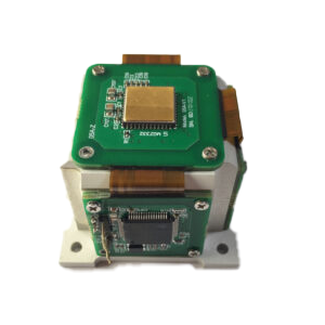
Because MEMS sensors are smaller and lighter, they are more sensitive to unmodeled temperature and vibration effects due to their mechanical properties. These effects increase noise (angular random walks) and lead to biases in the modeled noise figure. The IMU independently developed by Ericco Inertial Systems Co., Ltd. in China provides high-reliability, low-cost FOG/MEMS inertial measurement units to global customers. Ericco not only provides standard IMU products, but can also customize FOG/MEMS according to customers’ special requirements. For example, ER-MIMU-01 uses MEMS accelerometer and gyroscope with high quality and reliability, RS422 and external communication, baud rate can be flexibly set between 9600~921600, through the communication protocol to set the user’s required communication baud rate. With X, Y, Z three-axis precision gyro, X, Y, Z three-axis accelerometer with high resolution, can be output by RS422 X, Y, Z three axis of gyroscope and accelerometer’s original hexadecimal complement data (including gyro hexadecimal complement the numerical temperature, angle, the accelerometer hexadecimal temperature, the acceleration hexadecimal complement number); It can also output float dimensionless values of the gyroscope and accelerometer processed by the underlying calculation.
2.FOG IMU As the name suggests, FOG IMU is a type of IMU that uses optical fiber to measure the angular velocity or rotation rate of any object. Due to the low noise of fiber optic gyroscopes, this technology has been widely used in demanding navigation applications. FOGs are inherently more accurate and stable than MEMS-based systems, making them an alternative in scenarios where GNSS signals are unavailable (such as mining and navigation applications) or where GNSS denial may occur. Another notable feature of FOG is its rapid north-seeking capability. The FOG IMU can measure the Earth’s angular rotation and achieve heading in just minutes, even as the IMU itself moves.
Fiber optic gyroscopes use fiber optic loops and measure the interference of light beams in opposing loops to detect rotation about each axis. The hardware used is more expensive, larger and typically consumes more power, but its lack of moving parts makes it less sensitive to temperature changes and mechanical vibrations. And FOG gyrocompasses have no moving parts, making them more resistant to vibration and shock than MEMS gyrocompasses. This means they are ideally suited for applications that may experience intense vibration levels, such as demanding high temperature, high vibration environments such as mining, defence, surface ships and aerospace, and heavy equipment stabilization.
The ER-FIMU-50 FOG IMU is the most cost-effective inertial measurement device for navigation, control and dynamic measurements. This is the smallest FOG IMU developed by Ericco (same performance as KVH 1775). The system uses high-reliability closed-loop fiber optic gyroscopes and accelerometers, and uses multiple compensation techniques to ensure measurement accuracy. Strict technology is used in the manufacturing process to ensure that the angular and linear motion parameters of the carrier can be accurately measured under harsh conditions.
The product has a good user experience. In addition to wide voltage power supply, users can also configure the output bandwidth, data update rate, communication port baud rate and communication protocol as needed. It can be used in aviation track reference systems, guidance control systems, ship attitude measurement, inertial/satellite integrated navigation systems, drilling systems, mobile surveying and mapping systems, mobile satellite communications and other fields.
Differences between MEMS IMU and FOG IMU: Due to the different gyroscopes they have, these two types of IMUs are very different. Their 10 differences will be introduced below.
1.Technology: MEMS IMUs use microelectromechanical systems with accelerometers and gyroscopes based on micromachining technology.The FOG IMU uses a fiber optic gyroscope, which utilizes the principle of light interference in optical fibers.
2.Working principles: MEMS IMUs use the deflection of microstructures due to acceleration or rotation to measure motion. The FOG IMU measures motion by detecting the phase shift of light due to rotation in a fiber optic coil.
3.Accuracy: Compared to MEMS IMUs, FOG IMUs have higher accuracy and precision. This makes them particularly useful in situations where users rely on the IMU for long periods of time: accurate systems can calculate a position close to the true position even after hours.
4.Size and shape: MEMS IMUs are smaller and more compact, making them suitable for integration into smaller devices such as consumer electronics. FOG IMUs are typically larger and heavier, and are often used in larger systems such as aerospace and defense applications.
5.Cost: MEMS IMUs are generally more cost-effective than FOG IMUs, making them widely used in consumer products. FOG IMUs are more expensive due to their greater precision, highly specialized internal components, and complex advanced manufacturing processes.
6.Energy consumption: MEMS IMUs typically have lower power consumption, making them suitable for portable and battery-operated devices. FOG IMUs consume more power, which is less important in applications such as land vehicles and aircraft where power supplies are readily available.
7.Application: MEMS IMU can be used for north seeking in logging tools/gyro tools, pointing, steering and initial alignment in guided weapons/drone launch systems in advanced mining/drilling equipment, direction in satellite antennas, target tracking systems , pointing and tracking navigation-level MEMS guidance and navigation in weapon systems, directional railway train systems, navigation-level MEMS IMU/INS for precise attitude and position, measurement of north seeking and positioning in geodesy/land mobile mapping systems, Oil exploration, bridges, high-rise buildings, towers, dam monitoring, geotechnical monitoring, mining, etc. FOG IMUs are commonly used in aerospace, defense, marine navigation and other high-precision applications, particularly where GNSS is unavailable or unreliable, such as underground mining or military environments.
8.Robustness: MEMS IMUs can be susceptible to environmental factors such as extreme temperatures and high vibrations, which can affect their accuracy. The FOG IMU is more robust and stable, making it better suited for particularly harsh and demanding environments.
9.Calibration and automatic north seeking: Due to possible drift over time, MEMS IMUs may require more frequent calibrations to maintain accuracy. They are not sensitive enough to automatically find an accurate heading unless connected to a GNSS receiver. FOG IMUs have better long-term stability and typically require less frequent calibrations to maintain accurate heading or position. The most accurate fiber optic gyroscope systems are so sensitive that they can determine where north is by detecting the Earth’s rotation.
10.Integration: Because MEMS IMUs are smaller and have lower power requirements, they are easier to integrate into compact devices. FOG IMUs are typically used in larger systems to accommodate their size and weight and their higher power needs.
Selection of MEMS IMU and FOG IMU In summary, the choice of IMU depends on the application and environment. You can choose the IMU type that suits you according to different application scenarios, accuracy requirements, etc.
MEMS IMUs are ideal for: lightweight, small size, low power consumption, short-range pointing sensors, and GNSS integration in predictable dynamic environments.
FOG IMU is suitable for: absolute attitude accuracy, high temperature, high vibration, bias stability over time.
Accelerometer, as the name suggests, are used to measure acceleration, and today’s science and technology requires inexpensive, fully functional, and large-scale processing and production of accelerometer. In many fields, such as aerospace, machinery, and military industry, small and lightweight accelerometer are needed that can achieve many functions and are easy to test. The acceleration sensor integrated on the silicon chip has many advantages, micro acceleration sensor due to small and lightweight, conducive to mass production and other advantages, has been widely used in military, scientific measurement and other fields.
Micro accelerometer definition
Micro-electro mechanical systems (MEMS) are integrated miniature systems that combine electronic, mechanical, and other components, ranging in size from a few nanometers to micrometers, and are widely recognized in many fields. At present, micro acceleration sensor is one of the most widely used MEMS devices, which has the advantages of microfluidization, integration, intelligence, low cost, high performance and easy mass production. Applications range from smart phones, personal computers, the automotive industry and military defense. The micro-mechanical acceleration sensor based on MEMS technology has many advantages such as small size, light weight, fast start-up, low power consumption, easy integration, good reliability, strong anti-overload ability and low cost. According to the different types of sensitive signals, it can be divided into capacitive, piezoresistive and other micro acceleration sensors.
Structure and characteristics of capacitive micro-accelerometer
Capacitive micro acceleration sensor is the mainstream of MEMS acceleration sensor. Its basic structure is a capacitor composed of mass block and fixed electrode. When the mass block is displaced by acceleration, the capacitance pole area or distance is changed, and the acceleration is measured by measuring the capacitance. Capacitive micro accelerometersare the most common and mature products. The basic principle is to use the capacitor as a detection interface to detect the micro-displacement of the inertial mass due to the inertial force. The mass is supported by the elastic microbeam support on the substrate. One plate of the detection capacitor is generally disposed on the moving mass, and one plate is disposed on the fixed substrate. Figure 2 shows a typical sandwich-type flat capacitive micro accelerometer. Also, the capacitive micro accelerometer developed by AD uses a comb-tooth array capacitor as a detection interface. The capacitive micro accelerometer has high sensitivity and measurement accuracy, good stability, small temperature drift, low power consumption, and strong overload protection capability. It can realize feedback closed-loop control by using electrostatic force, which significantly improves the performance of the sensor.
For high-precision MEMS micro-accelerometers, performance stability is an important index of product quality. Under the same test conditions, such as temperature, humidity, etc., the repeatability of the same performance parameters of the device over a long period of time is called the stability of the device. Especially for capacitive MEMS micro accelerometers, due to changes in environmental factors or long-term storage, its zero drift and scale factors will change, thus reducing the accuracy of the device, resulting in long-term stability problems. Ericco introduced ER-MA-5,bias stability (Allan Curve)is 5μg, has the characteristics of small size, light weight, low energy consumption, can be widely used in vibration detection, attitude control, security alarm, consumer applications, motion recognition and state recording and other fields. The accelerometer is combined with a gyroscope and magnetometer to form an inertial measurement Unit (IMU).
At present, capacitive micro accelerometers have been gradually mature in the application of smart phone smart wearable medical and automotive industries. At the same time, with the continuous expansion of the market and technological upgrading, the application market of accelerometers continues to expand. Accelerometer application scenarios will have a broader space for development.
The range is the maximum range that can be measured by the sensor, which refers to the value of the difference between the upper and lower limits. Each sensor has its own measurement range, and when it is measured in this range, the output signal of the sensor has a certain accuracy. An acceleration sensor with a range of less than 1G is used as an inclination sensor, and a range of more than 1G is used as an acceleration sensor or vibration sensor. Because the larger the range, the less accurate. The biaxial tilt sensor ER-TS-4250VO can be selected in a range of +90°, while the uniaxial tilt sensor can be selected in a vertical direction of 360°.
2. Accuracy
In the process of testing and measurement, measurement errors are inevitable. There are two kinds of errors: systematic error and random error. The causes of system error, such as the inherent error of measurement principle and algorithm, inaccurate calibration, environmental temperature influence, material defects, etc., can be used to reflect the degree of influence of system error. The cause of random error is the gap of transmission components, aging of electronic components, etc. The precision can be used to reflect the influence of random error. Precision is a comprehensive index that reflects systematic error and random error, the higher the precision means the higher the accuracy and precision.
3. Zero offset
Zero drift means that when the input of the sensor is constant zero, the output value of the sensor will still change slightly to a certain extent. There are many reasons for zero drift, such as the change of the characteristics of the sensitive elements in the sensor with time, stress release, element aging, charge leakage, environmental temperature changes, etc. Among them, the zero drift caused by ambient temperature change is the most common phenomenon.
4. Input frequency
The frequency response characteristics determine the frequency range to be measured, and must allow the frequency range without losing the true measurement conditions, in fact, the sensor response will always have a certain delay. The higher the frequency response of the sensor, the wider the frequency range of the signal that can be measured, and the greater the interference. The lower the sensor frequency response, the narrower the frequency range of the signal that can be measured, and the lower the interference. In practical applications, a large number of measured signals are time changes, such as changes in current value, changes in object displacement, changes in acceleration, etc. This requires that the output of the sensor not only accurately reflect the size being measured, but also keep up with the speed of change being measured. In the frequency response range of the sensor, the amplitude of its output has a small change in the -constant range (maximum attenuation is 0.707). Therefore, when the input value is done sine
When changing, it is usually believed that the output value can correctly reflect the input value, but when the input value changes more frequently, the output value will produce significant attenuation, resulting in large measurement distortion.
5. Communication interface
RS232, TTL, RS485, RS232, CAN bus, voltage, current, SPI, IC, Profibus interface optional.If you want to learn more about tilt sensors or buy


.jpg)
