Wednesday, December 20, 2023

What is the Effect of Temperature Coefficient on Quartz Accelerometer?


 Quartz accelerometers, as one of the commonly used accelerometers, are mainly used to measure the acceleration of the carrier, it is a very important inertial device in the market.In the navigation and positioning of various carriers, the trajectory of the object can be obtained by measuring the acceleration, speed or position. However, because only the acceleration can be measured inside the moving object, the quartz accelerometer has a very important significance for inertial navigation technology.

The role of temperature coefficient

These core components are affected by temperature in practical applications, mainly in two aspects: first, the inertia device itself is sensitive to temperature, and the second is the device is affected by the surrounding temperature, that is, the temperature and the heat around the shell will cause errors within the device. The thermal expansion and cold contraction of the material will cause the deformation of the instrument structure parts, and the physical parameters of various internal materials will change accordingly, which directly affects the output stability, and then affects the navigation accuracy of the whole system. For this purpose, the ER-QA-03D can meet the normal operation in the operating temperature of -55℃ -180 ℃, and its offset repeatability reaches 50μg – 250μg, and the scale factor repeatability is 80 ppm – 250 ppm.

Temperature coefficient

Among the many indicators to measure the performance of quartz accelerometer, the stability of its offset value and scale factor are very important performance indicators, and also the prerequisite to ensure the high stability of quartz flexible accelerometer and even the high stability of inertial system. We know that the accuracy of inertial navigation system depends largely on the accuracy of inertial devices. The error of inertial navigation system is also formed by the accumulation of the error of inertial components in time, especially the inertial navigation system that needs to work continuously for a long time, the system error caused by the error of inertial components is astonishing.

Bias temperature coefficient

The offset value is the output value when the input acceleration of the quartz accelerometer is zero, and the change of the bias with temperature is called the offset temperature coefficient. The size and stability of the offset value is an important guarantee for the high linearity of the quartz accelerometer, especially when measuring small acceleration, the stability of the offset value is particularly important. The bias temperature coefficient of conventional accelerometers is about 30 ~ 100μg/℃. With the miniaturization of the inertial system and the requirement of low power consumption, the requirement of bias temperature coefficient is < 10 μg/℃ or even higher is put forward for the accelerometer. For example, the ER-QA-03A1 bias temperature coefficient can reach the range of < 10μg /℃, and the bias repeatability is ≤10μg and the scale factor repeatability is ≤15ppm. Based on the analysis and determination of the internal structure and properties of the material, the stability of the partial value affected by temperature is improved by the temperature compensating technology.

Scale factor temperature coefficient

The scale factor and its stability will directly affect the measuring accuracy of the accelerometer. Since the scale factor is determined by the common formula K1= = ml/Ktg, it is generally believed that ml (pendulum) and Ktg (torque coefficient of the torquer) are two factors that affect the change of the scale factor.It can be seen that the output scale factor is determined by the pendulum and the torque coefficient of the pendulum component. Because the quartz material is used, the thermal expansion coefficient is small, so the impact on the pendulum is small.In order to ensure the long-term repeatability of the scale factor of the quartz accelerometer, it is required to use high-performance permanent magnet materials. For the permanent magnet material used in the torquer, in fact, its stability largely depends on the stability of the magnetic system in various environments (including high temperature, low temperature, variable temperature, shock, overload, etc.). At present, the stability and repeatability of permanent magnet torquers and pendulum components are improved by screening more suitable permanent magnet materials combined with aging process.

From the above statement, it is not difficult to see the influence of temperature on the long-term stability of the quartz accelerometer. With the further study of the temperature coefficient of the offset value and scale factor, we can start from the relevant process technology to reduce the influence of temperature coefficient on the stability, so as to achieve the purpose of more accurate application of the quartz accelerometer.

The full text link :https://www.ericcointernational.com/application/what-is-the-effect-of-temperature-coefficient-on-quartz-accelerometer.html

If you want to know more about quartz accelerometers or purchase, please contact me through the following ways:
Email : info@ericcointernational.com
Whats app:1399288487

Tuesday, December 19, 2023

IMU working principle & Tactical grade IMU product recommendations

Nowadays, (Micro-electromechanical Systems, MEMS) inertial sensors and inertial systems have become an indispensable development direction of future navigation technology. MEMS technology has been widely used due to its advantages such as small size, light weight, low power consumption, low cost, and impact resistance. At present, the development of MEMS inertial technology is relatively mature. It forms a combined system with auxiliary systems such as gyroscopes and accelerometers, which can provide appropriate solutions for most navigation applications. The Inertial Measurement Unit developed by Ericco are divided into MEMS IMU and FOG IMU. MEMS inertial measurement units are divided into tactical grade and navigation grade. Navigation-level IMUs can independently seek north, while tactical-level Inertial Measurement Units can rely on magnetometers or GNSS to find north. The following will be divided into two parts: an introduction to the working principle of the inertial measurement unit and a product introduction of ERICCO’s tactical-level IMUs.

How the MEMS Inertial Measurement Unit works: 

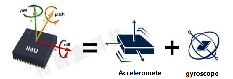
The inertial measurement unit is a device that measures the three-axis attitude angle (or angular rate) and acceleration of an object. Generally, an inertial measurement unit contains three single-axis accelerometers and three single-axis gyroscopes. The accelerometer detects the acceleration signals of the object in three independent axes of the carrier coordinate system, while the gyroscope detects the angular velocity signal of the carrier relative to the navigation coordinate system. Measure the angular velocity and acceleration of the object in three-dimensional space, and use this to calculate the attitude of the object. It has very important application value in navigation. IMUs are mostly used in equipment that require motion control, such as cars and robots. It is also used in situations where precise displacement calculations using attitude are required, such as inertial navigation equipment for submarines, aircraft, missiles and spacecraft.

The principle of an inertial measurement unit is very similar to taking small steps in the dark. In the dark, due to the error between your estimate of the step length and the actual distance traveled, as you take more and more steps, the difference between your estimated position and the actual position will become farther and farther. When taking the first step, the estimated position is relatively close to the actual position; but as the number of steps increases, the difference between the estimated position and the actual position becomes larger and larger. This method is extended to three dimensions, which is the principle of the inertial measurement unit.

The academic expression is: Based on Newton’s laws of mechanics, by measuring the acceleration of the carrier in the inertial reference system, integrating it over time, and transforming it into the navigation coordinate system, the velocity in the navigation coordinate system can be obtained. , yaw angle and position information.

Therefore, in layman’s terms, the inertial measurement unit is a strapdown inertial navigation system. The system consists of three acceleration sensors and three angular velocity sensors (gyros). The accelerometer is used to feel the acceleration component relative to the vertical line of the ground. The speed sensor is used to get a feel for the angle information.

It is worth noting that the inertial measurement unit provides relative positioning information. Its function is to measure the movement route of the object relative to the starting point, so it cannot provide information about your specific location. Therefore, it is often combined with GPS. Used together, when the GPS signal is weak in certain places, the IMU can play its role, allowing the car to continue to obtain absolute position information and not get “lost.”

ERICCO tactical grade inertial measurement unit

Next, we will mainly learn about a new inertial measurement unit – ERICCO INERTIAL SYSTEM tactical-grade inertial measurement unit: ER-MIMU03(High Precision Navigation/Stable Control MEMS IMU).

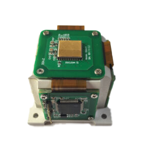
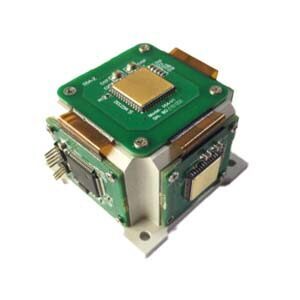
ERICCO launches a tactical-grade inertial measurement unit (IMU): ER-MIMU03 uses high-quality and reliable MEMS accelerometers and gyroscopes. Equipped with X, Y, Z three-axis precision gyroscope, X, Y, Z three-axis accelerometer, with high resolution, it can output the original hexadecimal complement of X, Y, Z three-axis gyroscope and accelerometer through RS422 code data (including gyroscope hexadecimal complement) numerical temperature, angle, accelerometer hexadecimal temperature, acceleration hexadecimal complement); it can also output gyroscope and accelerometer data that have been processed by underlying calculations Floating point dimensionless value. ). The IMU has a built-in acceleration sensor and gyroscope, which can measure linear acceleration and rotational angular velocity in three directions, and obtain the attitude, speed and displacement information of the carrier through analysis. Applications for this tactical-grade IMU include azimuth, attitude, position measurement and maintenance in GNSS-assisted INS. Heading, pitch, roll measurement in UAV AHRS Robot control and control Autonomous machines, unmanned vehicle directional stabilization and control satellite antenna pointing, target tracking system Guidance, navigation and control attitude and attitude IMU in tactical MEMS weapon systems The azimuth angle is maintained and positioned. Movement investigation and maintenance in MRU and other application areas.

High Precision Navigation/Stable Control MEMS IMU integrates a three-axis MEMS accelerometer and a three-axis MEMS gyroscope in a unique redundant design, which can maximize performance while reducing device size.

In terms of performance specifications, the High Precision Navigation/Stable Control MEMS IMU has an excellent gyroscope and accelerometer. The bias instability of the gyroscope is 0.3°/h. Enables long-term dead reckoning and maintains excellent heading performance. The MEMS sensor in ER-MIMU03 has extremely low vibration correction errors and can withstand high vibration environments up to 6.06g.

With very low gyro bias instability, the navigation performance of High Precision Navigation/Stable Control MEMS IMU can work well when GNSS is interfered with or has no signal. This tactical-grade IMU has relatively high accuracy compared to tactical-grade IMUs from other peer companies. If you want to purchase our IMU, please contact our relevant personnel.

Knowledge about Accelerometer


 Accelerometer is an instrument  that uses Newton’s second law (Law of inertia) for measuring the acceleration of the carrier line. The accelerometer is one of the first aircraft instruments to be used for measuring aircraft overload. Accelerometer consists of test quality (also known as sensitive mass), support, potentiometer, spring, damper and shell. Accelerometer is commonly used to monitor engine failures and fatigue damage of aircraft structures.The performance levels of different kinds of inertial accelerometers can be divided into navigation level, tactical level and consumer level.

Development of quartz accelerometers

Accelerometers originated in the 1940s, many new accelerometers appeared in the 1950s, and further improved in miniaturization, low cost, multi-function and high stability in the 1960s, MEMS accelerometers were born and became a technological development trend in the late 1970s, and quantum accelerometers began to be developed in the early 21st century. Become a representative of the future ultra-high precision accelerometer.

Application characteristics

The accelerometer is an important part of the inertial measurement unit (IMU), and together with the gyroscope determines the accuracy of more than 90% of the inertial navigation system, its cost, size, weight and power consumption characteristics on the inertial navigation system (INS) application field also has a greater impact, different application fields have different requirements for the use of the accelerometer.

In the flight control system, accelerometer is an important dynamic characteristic correction element.In inertial navigation system, the high precision accelerometer is one of the most basic sensitive components.The accelerometer in different use situations is different in performance. The high precision inertial navigation system requires the accelerometer to have a resolution of 0.001g, but the range is not large. An accelerometer that measures an aircraft’s overload may require a range of 10g, while the accuracy is not high.For example, ER-QA-03A has bias repeatability of 10-50μg, scale factor repeatability of 15-50 PPM and Class II non-linearity repeatability of 10-30μg/g2 with a resolution of 5μg, so it is a good choice for flight control systems.

In the field of oil and gas drilling, the complex formation structure and the continuous upgrading of drilling technology put forward higher requirements for drilling tools. When measuring the attitude parameters of the steering drilling tool, the tool rotation, near-bit vibration and downhole high temperature and pressure will seriously affect the measurement accuracy of the tool attitude parameters. In order to better overcome these factors to obtain accurate measurement data information, ER-QA-03D can not only meet the temperature environment of -40℃ -180 ℃,  anti-shock is 500-1000g 0.5ms, but also bias repeatability  has 50μg – 250μg .

Key technology

Flexible bracing

The function of flexible support is to convert the change of input acceleration into the change of vibration force of the beam, and then into the change of output frequency. Generally, quartz materials with good strength, high fatigue strength, non-magnetic and good processing ability are used. The design of flexible support combined with the process can be used flat bridge type or arc type. As the key parts of quartz vibration beam accelerometer, the thickness, stiffness and symmetry of flexible joint machining have an impact on the accuracy of the instrument.

Temperature compensation

Temperature is an important aspect that affects the accuracy of quartz accelerometer. The fluctuation of the operating temperature inside the inertial device and the heat source around the shell will cause the error of the output data. The thermal expansion and contraction of the material will deform the structural parts of the accelerometer, and the temperature change will also cause certain changes in the physical parameters of various materials inside the device. The change of the magnetic properties of the torquer will also directly affect the measurement accuracy of the accelerometer. Therefore, through the technology of temperature compensation, the accuracy of the accelerometer can be improved to a certain extent.

Through the above content, we have a preliminary understanding of the related knowledge of the accelerometer other information, for more information, please feel free to contact info@ericcointernational.com

Email : info@ericcointernational.com

Whats app:1399288487
What is the Difference between Single, Double, Three axis in Tilt Sensor


Axial and spatial dimensions of tilt sensors

The conventional spatial dimension is composed of length, width and height, and the inclination sensor can measure the inclination angle of these three dimensions. Therefore, the inclination sensor can be divided into single axis, two axis and three axis according to the axis. Single-axis tilt sensor can only measure the angle of a certain azimuth; The biaxial tilt sensor can measure the angle of two perpendicular azimuths. The three-axis can measure the angle of transformation of the three directions around the arbitrary axis in three-dimensional space.

Single axis, double axis, triple axis 

Inclination sensors usually refer to single-axis tilt sensors, and the theoretical basis of single-axis inclination sensors is Newton’s second law. According to the basic principles of physics, inside a system, velocity cannot be measured, but acceleration can be measured. If the initial velocity is known, the linear velocity can be calculated from the integral, and thus the linear displacement can be calculated. So it’s actually an acceleration sensor that uses the basic principles of inertia. The dual-axis inclination sensor is based on the single axis combined with specific practical requirements, designed and conceived a measurement tool for the angle between two directions.

Based on the direct measurement of the acceleration of the measured object, the biaxial inclination sensor can obtain the linear velocity of the object through integral calculation, and then further obtain the displacement of the object. In essence, the inclination sensor is still an inertial sensor, which follows the inertia law of object motion and the integral calculation method. The two-axis sensor is designed in view of this basic principle, in addition to other measurement principles and measurement methods.

In short, the dual-axis in tilt sensor has the measurement advantages of the single-axis inclination sensor, but also has the measurement effect that can not be achieved by the single axis, with an increasingly wide measurement range. However, the accuracy of the dual-axis inclination sensor is not as good as that of the single axis, and it should be noted that the dual-axis inclination sensor can measure the angle of the X-axis and the Y-axis, but can not measure the X-axis and the Y-axis at the same time, only one axial angle can be measured at a time, the X-axis or the Y-axis, if measured at the same time, it will cause the horizontal axis error and cannot determine its value. Depending on the desired measurement data, you can choose different tilt sensors. In theory, if there are three dimensions of angle change, you need to use a three-axis inclination sensor, but in reality, the three-axis inclination sensor does not exist, more accurately, the two-axis inclination sensor can measure the three-dimensional angle change, without using the so-called “three-axis inclination sensor.” As for why there is no three-axis inclination sensor, it is because when the inclination angle of a incline plane and the X and Y axes is determined, the incline plane is fixed, and there is no possibility of change, that is, the angle between the Z axis is also a definite value.

Taking the X-axis uniaxial tilt sensor as an example, the measuring surface of the sensor can only have an angle with the X-axis, and the inclination plane is fixed on one axis (Y-axis) for rotation. Similarly, the Y-axis uniaxial inclination sensor rotates with the X-axis as the fixed axis. The inclination plane of the biaxial inclination sensor can have an angle with both the X and Y axes, or only one of the axes can have an angle, which is the general case of the inclination plane of the biaxial inclination sensor.

From the above comparative data analysis of the uniaxial and biaxial inclination sensors, it can be seen that the active part of the inclination plane of the biaxial inclination sensor is a point or line, while the single axis can only be a line. For example, the inclination of the vertical wall is the active part of the combination line between the wall and the foundation, which can be measured by the single-axis inclination sensor ER-TS-3160VO; The process of slow toppling of a vertical rod is based on the contact point as the active part, so it is necessary to use the dual-axis inclination sensor ER-TS-4250VO for measurement. In fact, in the process of tilting the vertical rod, no matter which direction it tilts, one thing is certain, that is, the angle between the tilting position and the original position is the angle between the tilting plane and the horizontal plane, this angle may only be a single X or Y axis inclination, or both, which is why it can only be measured with a dual-axis inclination sensor. 

Monday, December 18, 2023

Tilt sensors for Wireless Positioning Anti-theft Tracking Systems in Vehicle


 Ericco’s tilt sensor can be well used in the wireless positioning anti-theft tracking system.

The vehicle load wireless positioning anti-theft tracking system receives vehicle sensor fusion information through the main controller of the vehicle, obtains GPS satellite positioning information through the GPS module, and then communicates bidirectional with the user terminal through the public mobile communication module through the public mobile communication base station, and sends out local sound and light alarm, GSM wireless transceiver, and realizes mobile and instantaneous control. The sensor fusion information is obtained by the inclination sensor, microwave Doppler sensor trigger infrared sensor, vibration sensor, Hall switch element and air pressure sensor after extraction, fusion and decision, and the user terminal sends control instructions to the master controller after identity verification to realize intelligent zero false alarm automatic monitoring.

Ericco ER-TS-4156DI tilt sensor can be well used in the control system, the control part and the execution part, the tilt data acquisition part includes the tilt sensor with GPS module, the signal output interface of the tilt sensor and the MCU analog to digital conversion interface of the control part. The signal end of the ignition lock is connected with the input and output interface of the single chip microcomputer: the single chip microcomputer is connected with the GSM module through the serial port; The user's mobile phone number and other personal information are preset in the single chip computer. The execution part includes the control circuit of the relay that controls the main control power supply of the vehicle and the input and output interface of the single chip microcomputer, and the vehicle alarm system and the input and output interface of the single chip microcomputer. The inclination sensor can not only measure the form attitude of the vehicle body, but also provide the location of the vehicle, provide reliable latitude and longitude for the tracking system, and shorten the detection time.

If you want to learn more about tilt sensors or buy

Please contact me in the following ways:

Email: info@ericcointernational.com

Whatsapp: 13992884879

Friday, December 15, 2023

Inertial measurement unit


Introduction
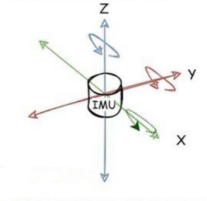
Inertial measurement units are one of the most common sensors in navigation. It contains an accelerometer and gyroscope, and sometimes a magnetometer and barometer. The accelerometer is responsible for the acceleration measurement, while the gyroscope is responsible for the angular velocity measurement. Each of these measurements is expressed along the three-axis coordinate system x,y,z. An inertial measurement unit is a device that measures three-axis attitude (or angular velocity) and acceleration. To increase reliability, it is also possible to equip each axis with more sensors. Generally, the IMU should be installed at the center of gravity of the object being measured.

IMUs are commonly used to control modern vehicles, including missiles, robots, submarines, aircraft (attitude and heading reference systems), including unmanned aerial vehicles (UAVs), etc., and spacecraft, including satellites and landers. Developments in recent years have allowed the production of IMU-enabled GPS devices. The IMU allows the GPS receiver to operate when the GPS signal is unavailable, such as in tunnels, inside buildings, or when there is electronic interference.

Operating principle
An inertial measurement unit (IMU) works by detecting linear acceleration using one or more accelerometers and measuring angular velocity using one or more gyroscopes. Some also include magnetometers. Pitch, roll and yaw are commonly used as attitude reference systems.

Instructions
The IMU is often integrated into an inertial navigation system, which uses raw IMU measurements to calculate the attitude of the drone. A simpler version of the INS, called an Attitude and Heading Reference System (AHRS), uses an IMU to calculate the vehicle’s heading attitude relative to magnetic north. Data collected from the IMU sensors allows computers to track the aircraft’s position using a method called dead reckoning.

In land vehicles, IMUs can be integrated into GPS-based car navigation systems or vehicle tracking systems, giving the system dead reckoning capabilities and the ability to collect as much information as possible about the vehicle’s current speed, turn rate, heading, inclination and acceleration. The accurate data with the vehicle’s wheel speed sensor output as well as the reverse gear signal (if available) are used for better purpose traffic collision analysis.

In addition to navigation purposes, IMUs are used as orientation sensors in many consumer products. Almost all smartphones and tablets contain an IMU as an orientation sensor. Fitness trackers and other wearable devices may also contain IMUs to measure movement, such as running. The IMU is also able to determine an individual’s developmental level while exercising by identifying the specificity and sensitivity of specific parameters related to running. Some gaming systems use IMUs to measure motion. Low-cost IMUs have fueled a boom in the consumer drone industry. They are also frequently used in sports technology (technical training) and animation applications. They are competing technologies for motion capture technology.

In a navigation system, data reported by the IMU is fed into a processor that calculates altitude, speed, and position. A typical implementation called a strapdown inertial system integrates the angular rate of a gyroscope to calculate angular position. It is fused with the gravity vector measured by the accelerometer in a Kalman filter to estimate the attitude. Attitude estimation is used to convert acceleration measurements into an inertial reference frame (hence the name inertial navigation), where they are integrated once to obtain linear velocity and twice to obtain linear position.

For example, if an IMU installed in an aircraft moving along a certain direction vector will measure the aircraft’s acceleration as 5 m/s2 for 1 second, after 1 second the guidance computer will infer that the aircraft must be flying at 5 m/s, and Must be 2.5 m from the initial position (such as a satellite or terrestrial radio transponder, although external sources are still used to correct for drift errors, and since the position inertial navigation system allows the update frequency to be higher than the smoothness of the vehicle motion can be perceived on the map display This method of navigation is used in conjunction with a system called GPS (because the navigation system position output is often used as a reference point to produce a moving map), the guidance system can use this method to show the pilot the aircraft’s geographical position at a certain moment in time. Like a moving map display.

A major disadvantage of using IMUs for navigation is that they are often affected by accumulated errors. Because the guidance system continuously integrates acceleration versus time to calculate velocity and position, any measurement error, no matter how small, accumulates over time. This results in “drift”: a growing discrepancy between where the system thinks it is and where it actually is. Due to integration, a constant error in acceleration results in a linear error growth in velocity and a quadratic error growth in position. A constant error in the attitude rate (gyro) results in a quadratic error growth in velocity and a cubic error growth in position.

IMU performance

There are many types of IMUs, depending on the application type, with performance ranges:

Gyroscope from 0.1°/s to 0.001°/h (angular velocity random walk)

Accelerometers from 100 mg to 10 µg (bias repeatability)

Roughly speaking, this means that for a single uncorrected accelerometer, the cheapest (100 mg) loses its ability to provide 50 meter accuracy after about 10 seconds, while the best accelerometer (10 mg) Lost the ability to provide 50 meter accuracy. µg) loses accuracy over 50 meters after approximately 17 minutes.

The accuracy of the inertial sensors within the inertial measurement unit (IMU) has a more complex impact on the performance of the inertial navigation system (INS).

The behavior of gyroscope and accelerometer sensors is usually represented by errors based on the following, assuming they have appropriate measurement range and bandwidth:

1.Offset error: This error can be divided into stability performance (the drift of the sensor under constant conditions) and repeatability (the error between two measurements under similar conditions, but with different intermediate conditions).

2.Scale factor error: First-order sensitivity error due to non-repeatability and nonlinearity.

3.Misalignment error: due to imperfect mechanical installation.

4.Noise: Depends on required dynamic performance.

5.Environmental sensitivity: mainly sensitivity to thermal gradients and acceleration.

All of these errors depend on various physical phenomena unique to each sensor technology. Depending on the target application and to be able to make the right sensor selection, it is important to consider the needs in terms of short- and long-term stability, repeatability, and environmental sensitivity (mainly thermal and mechanical environments). In most cases, the target performance of the application is better than the absolute performance of the sensor. However, sensor performance is repeatable over time, with more or less accuracy, so it can be evaluated and compensated to enhance its performance. This real-time performance enhancement is based on sensor and IMU models. The complexity of these models will then be chosen based on the performance required and the type of application being considered. The sensor and IMU models are calculated at the factory through a dedicated calibration sequence using a multi-axis turntable and a climate chamber. They can be calculated for each individual product or generally for the entire production. Calibration typically improves a sensor’s original performance by at least twenty years.

Assemble
High-performance IMUs or IMUs designed to operate in harsh conditions are often suspended by shock absorbers. These shock absorbers need to master three effects:
1.Reduce sensor errors due to mechanical environmental requirements.
2.Protect sensors as they may be damaged by shock or vibration.
3.Contain spurious IMU motion within a limited bandwidth that processing will be able to compensate for.

Reducing these errors often prompts IMU designers to increase processing frequencies, and this is made easier with the latest digital technology. However, developing algorithms that can eliminate these errors requires deep inertial knowledge and a close understanding of sensor/IMU design. On the other hand, if suspension has the potential to improve IMU performance, it will have side effects on size and mass. The ER-MIMU01 product developed by Ericco uses a three-axis gyroscope and a three-axis accelerometer. Below are the important parameters of the gyroscope and accelerometer added to the ER-MIMU01 model IMU:

Gyro (ER-MG2–100 (0.02°/hr))

Bias instability:<0.02

Bias stability (1σ 10s): <0.1deg/hr

Bias stability (1σ 1s): <0.3deg/hr

Bias repeatability (1σ): <0.1deg/hr

Accelerometer (range: 2–10g)

Bias Repeatability: 100–300ug

Bias Repeatability: <500ppm

Class II Non-linearity Coefficient: <100ug/g2

Accelerometer (range: 10–30g)

Bias Repeatability: 200–500ug

Bias Repeatability: <500ppm

Class II Non-linearity Coefficient: <100ug/g2

If you are interested in the imu studied by Ericco, please contact us.

website:https://www.ericcointernational.com/inertial-measurement-units

WhatsApp: +8613992884879

Email: info@ericcointernational.com

Thursday, December 14, 2023

What are the Advantages and Disadvantages of Quartz Accelerometers?


As one of the products of inertial sensor, quartz accelerometers are  the basic measurement element of inertial navigation and inertial guidance system, and their  speed and position are obtained by integrating the acceleration. They work on the basis of Newton’s second law, which state that the resultant force on an object is equal to its mass times its acceleration. Therefore, the performance and accuracy of the accelerometer directly affect the accuracy of the navigation and guidance system, and we will briefly understand its advantages and disadvantages.

The advantages of quartz accelerometers

High precision and sensitive

The quartz accelerometer uses digital signal processing technology, the reaction speed is very fast, and it can respond to acceleration changes in an instant. At the same time, it has the characteristics of high precision and high sensitivity. It can accurately measure the acceleration change of the object during the movement and output it as a digital signal. This feature of high precision and high sensitivity. For example, the zero-bias stability of ER-QA-03A is 10-50μg, the scale factor is 15-50 PPM, and the second-order nonlinearity is 10-30μg/g2, which provides accurate data support in the industrial field to help engineers perform accurate motion control and analysis.

Small size and light weight

In the case of limited carrier space design size, this allows small quartz accelerometers to be conveniently installed in a variety of equipment and structures without placing too much burden on them. The small size and light weight also mean that acceleration sensors can operate in limited Spaces and have high reliability. The ER-QA-03F is a small accelerometer with a diameter of Φ18.2mm, a scale factor of 150-220 PPM, and a second-order nonlinearity of 40-50μg/g2. Compared with products with the same parameters, this accelerometer is a good choice for equipment that can meet the requirements of relevant parameters and meet the strict requirements of space.

Strong ability to adapt to temperature

Quartz accelerometers have a wide operating temperature range. Whether it is in an extremely cold environment or in a high temperature environment, it can work normally. This makes its application in extreme conditions possible. Such as aerospace, deep sea exploration and oil and gas drilling fields. ER-QA-03D can operate normally at a working temperature of -55~180 ° C, and its volume of 25×21mm, impact resistance 500-1000g 0.5ms. The acceleration sensor has the function of self-diagnosis and fault detection. With internal algorithms and automatic calibration, the accelerometer detects and corrects its own faults, ensuring data accuracy and reliability. This self-diagnosis and fault detection capability helps reduce maintenance costs and increase productivity.

The Disadvantages of quartz accelerometers

Temperature effect

In the long-term high temperature environment, the working accuracy of the quartz accelerometer will be affected by the temperature, because the crystal lattice structure changes will lead to changes in the resonant frequency, so the temperature needs to be compensated or used in the appropriate temperature range.

Complex structure

The structure of quartz vibration beam accelerometer is relatively complex, and the manufacturing process requires a high level of technology, so the cost is high.

High cost

The manufacturing and maintenance cost of inertial navigation and positioning system is high, requiring the use of precision instruments to manufacture and debug, and the maintenance cycle is short and the maintenance cost is high.

This paper introduces the advantages of quartz accelerometer such as high precision, high sensitivity, temperature influence, complex structure and high cost, but with the development of quartz accelerometer technology, these disadvantages can be further optimized.

 text  link:https://www.ericcointernational.com/application/what-are-the-advantages-and-disadvantages-of-quartz-accelerometers.html

Choose a suitable IMU to make your drone flight more stable and safe

         As one of the core components of drones, IMU plays an irreplaceable role. Its high precision, fast response and freedom from extern...