Wednesday, January 10, 2024

Analysis of Influencing Factors of Accelerometer Machining and Assembly


The precision of the quartz accelerometer is closely related to its processing and assembly accuracy during production. Accelerometer is a kind of instrument with complicated production process, and a large number of uncertain factors are introduced in processing and assembly. It is helpful to improve the accuracy of accelerometer by analyzing it in detail.  

1) Processing technology

The components of quartz accelerometer have the characteristics of thin wall, high precision, complex shape and small size in structure. In the process of machining and assembly, the manufacturing accuracy, shape error and dimensional accuracy are all up to μm level. However, these parts will introduce some uncertain factors in the assembly process, so the whole process will inevitably introduce small errors. The structure of the accelerometer itself is relatively compact, and these small errors will inevitably affect the performance of the accelerometer.   

Quartz crystal is the main component of quartz pendulum, it is a brittle non-metallic material, with high strength, high hardness, low conductivity and low fracture toughness characteristics. It is different from common metal materials, processing methods have a great impact on its strength, and any improper processing technology will affect the reliability, fracture strength and surface integrity of the quartz surface. At present, the commonly used processing method is laser cutting and chemical corrosion method, but this method has more procedures, and requires complex processes such as plugging, masking, and clamping. Experienced workers should also accurately grasp the corrosion time and acid temperature. Therefore, in order to improve the processing accuracy and efficiency, it is necessary to study the new processing technology.

2) Assembly technology

Assembly process quality directly determines the performance of the accelerometer. At present, the assembly process of the accelerometer is still using the traditional manual operation. The production acceleration timing adopts the assembly process of first trial assembly and then test. However, due to the large number of assembly links, it is difficult to accurately find the factors causing performance decline. Moreover, its performance is closely related to the operating habits, operating skills, experience knowledge, proficiency and other factors of assembly workers, resulting in the performance of the accelerometer after production being approximately normal distribution. The rate of special products is low. Therefore, in order to design a small-range and high-precision quartz flexible pendulum accelerometer and improve the overall performance of the accelerometer, it is necessary to consider the impact of processing and assembly technology on its performance, and scientifically improve the processing technology and assembly process of the accelerometer to reduce the manufacturing difficulty.

The quartz accelerometer ER-QA-03A produced by Ericco uses mature processing technology to ensure that it meets the demand for accuracy during use.

Web:https://www.ericcointernational.com/accelerometer/quartz-accelerometer

Email : info@ericcointernational.com

Whats app:1399288487

Tuesday, January 9, 2024

Application of Tilt Sensor in Railway Monitoring


 Railway transportation is one of the most important modes of transportation in China, and it has been developing continuously in recent years, with bullet trains, high-speed trains, intercity trains, and train speeds getting faster and faster. However, with greater speed comes greater danger, and accidents abound.

Although the state requires the limit of speed, but the limit of speed can not solve the fundamental problem, how to ensure driving safety, to create a stable and efficient driving environment is the most urgent need at present.

The train is a special means of transport running on the railway track. Its use environment is complex and changeable, and it is often affected by various factors such as wind, snow, earthquake, debris flow, landslide, tunnel foreign matter, geological mutation, etc. It is easy to cause deformation of the railway track and be covered by foreign matter, which seriously threatens the safety of the train.

Ericco’s tilt sensor measurement accuracy of 0.01°, not only can accurately measure the inclination of the track, deformation, but also real-time monitoring of the inclination of the surrounding environment of the track, especially in some places rarely visited, in advance to make a preventive alarm, to avoid the occurrence of major accidents.

If you want to learn more about tilt sensors or buy tilt sensor

Please contact me in the following ways:

Email: info@ericcointernational.com

Whatsapp: 13992884879

What Does IMU Mean for A Drone?

Definition of drone:


The full name of “unmanned aircraft” is unmanned aircraft, which is operated by radio remote control equipment and self-provided program control devices, or by the on-board computer fully or intermittently autonomous operation. In order to make the UAV fly perfectly, IMU(Inertial Measurement Unit), gyroscope stabilization and flight controller technology are essential.


Working principle


The flight control of UAV is composed of main control MCU and inertial measurement module IMU. IMU provides the original sensor data of the aircraft’s attitude in space, and the data of the aircraft is generally provided by the gyroscope sensor/acceleration sensor/electronic compass. Gyroscopic stabilization technology is one of the most important components, allowing the drone to fly super-smoothly even in strong winds and gusts. This smooth flight allows us to take fantastic aerial views of the beautiful planet. With excellent flight stability and waypoint navigation, the UAV can generate high-quality 3D photogrammetry and liDAR images. The latest drones use an integrated head, which also includes built-in gyroscopic stabilization technology, so that the on-board camera or sensor has little to no vibration. This allows us to capture perfect aerial film and photographs. In order to meet the requirements of UAV equipment, the ER-MG2-300/400 gyroscopes not only use advanced differential sensor design, can eliminate the effects of linear acceleration and operate in the presence of shock and vibration in the extremely harsh environment, but also have a measurement range of 400 degrees/second and 0.01°/ hour bias instability. Capable of measuring angular velocities up to ±400°/s and has a digital output protocol compliant with SPI from mode 3. Angular rate data is expressed as 24-bit words.


Technical influence


The application of IMU in UAVs is not limited to attitude control and flight stability. It can also be used with other sensors such as GPS (Global Positioning System) and magnetometers to provide more accurate navigation and positioning information. At the same time, IMU can also be used for UAV attitude estimation, motion detection, obstacle avoidance and other functions, improve the autonomy and safety of the UAV, provide key data for the control and navigation of the UAV, so that the UAV can efficiently perform various tasks. The application of IMU will vary depending on the design and use of different types of UAVs, but whether it is fixed wing, multi-rotor or vertical take-off and landing and conversion UAVs, IMU is the core to achieve its flight control and navigation.

If you want to learn about or purchase IMU, please contact us


contact me:

website:https://www.ericcointernational.com/inertial-measurement-units

Email: info@ericcointernational.com

WhatsApp: +8613992884879


Application of Tilt Sensor in Vehicle Four-wheel Positioning


Tilt sensor in the four-wheel locator

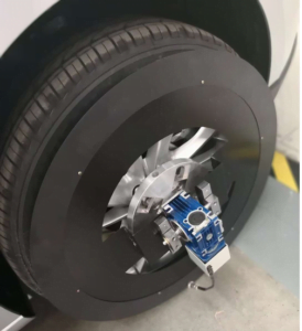
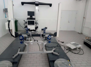
For different four-wheel positioning equipment, the key role is to measure the accuracy of the tilt sensor. Modern cars generally adopt front and rear independent suspension, and the main parameters detected by the four-wheel alignment instrument are wheel camber, kingpin rear angle, kingpin internal angle and front bundle. For the measurement of the above tilt angles, except the front beam angle is generally realized by the rotary disk or the angle sensor, and the other angles are generally adopted by the tilt sensor. The tilt sensor is fixed on the four-wheel alignment mounting plate, and then installed on the wheel of the car through the clamp.

Due to the reason of automobile structure, the tilt measurement of automobile wheel positioning angle is divided into direct measurement and indirect measurement. From the definition of wheel inclination, it can be seen that the measurement of wheel camber can be measured directly by the tilt sensor, while the kingpin internal inclination and kingpin rear inclination are not, because the kingpin is installed on the inside of the wheel, generally can not be measured directly by the tilt sensor. The measurement range of wheel inclination should be about ±15°. In today’s models, the inclination adjustment deviation value is generally about 5′, such as: Shanghai Volkswagen PASSAT B5 front wheel camber value is -0°35′ to ±0°25′, so the sensor measurement resolution should be less than or equal to 5′.

Application of Tilt Sensor in Vehicle Four-wheel Positioning

What is car four-wheel positioning?

From the structure of the car, the car’s steering wheel (front wheel), steering knuckle and front axle installation between the three has a certain relative position, this installation with a certain relative position is called steering wheel positioning, also known as front wheel positioning. Front wheel positioning includes

Kingpin back tilt (angle), kingpin inward tilt (angle), front wheel outward tilt (angle) and front wheel front bundle four contents. For the two rear wheels, there is also a relative position between the installation and the rear axle, called the rear wheel positioning. Rear wheel positioning includes wheel roll out (angle) and one rear wheel front bundle. In this way, the front wheel positioning and the rear wheel positioning are called four-wheel positioning.

When the vehicle leaves the factory, the positioning angle is pre-set according to the design requirements. These positioning angles are used together to ensure the driving comfort and safety of the vehicle. However, because the vehicle is sold and driven for a period of time, these positioning angles will change due to traffic accidents, severe bumps caused by uneven road potholes (especially when driving at high speed suddenly encounter uneven roads), chassis parts wear, chassis parts replacement, tire replacement and other reasons. Once the positioning angle changes due to any reason, it may produce uncomfortable symptoms such as abnormal tire wear, vehicle deviation, reduced safety, increased fuel consumption, accelerated wear of parts, heavy direction, and vehicle drift. Some symptoms make the vehicle very dangerous at high speeds.

Application of Tilt Sensor in Vehicle Four-wheel Positioning1

What is a four-wheel locator?

The purpose of four-wheel positioning maintenance service is to diagnose and treat the above causes of vehicle discomfort by measuring the positioning Angle. Generally, the new car should be four-wheel positioning after 3 months of driving, and every 10,000 kilometers after driving, replacing the tire or shock absorber, and after the collision should be timely four-wheel positioning. The correct positioning of the wheel can ensure that the steering is flexible, the seat is comfortable, the straight line driving is maintained, the life of the tire is extended, and the vibration caused by the road is reduced.

At present, most of the instruments used for wheel positioning detection are “four-wheel positioning instrument”. During the detection, the four-wheel positioning instrument first measures the current four-wheel positioning parameters of the car, and then the computer automatically compares it with the stored value of the corresponding model to calculate the deviation value of the four-wheel positioning of the car, and the maintenance personnel can restore the original state by correcting the prompts of the positioning instrument.

In Summary:

Ericco introduces the ER-TS-4256DI1, a tilt sensor for automotive four-wheel aligners, which has multiple interfaces and can be easily embedded into user systems. It can resist external electromagnetic interference, adapt to the harsh industrial environment for long-term work, is the ideal choice for industrial automation control and platform attitude measurement. The main features are as follows:

Biaxial dip measurement (X and Y) 

Resolution less than 0.01°, accuracy 0.1°

Single PCB board, easy to embed into the user circuit system

Single power supply, digital signal (RS485) output

Built-in temperature sensor (digital SPI output)

Vibration resistance 3500g  

Monday, January 8, 2024

Differences between MEMS IMU and FOG IMU


Due to the different gyroscopes they have, these two types of IMUs are very different. Their 10 differences will be introduced below.

1.Technology:
MEMS IMUs use microelectromechanical systems with accelerometers and gyroscopes based on micromachining technology.The FOG IMU uses a fiber optic gyroscope, which utilizes the principle of light interference in optical fibers.

2.Working principles:
MEMS IMUs use the deflection of microstructures due to acceleration or rotation to measure motion.
The FOG IMU measures motion by detecting the phase shift of light due to rotation in a fiber optic coil.

3.Accuracy:
Compared to MEMS IMUs, FOG IMUs have higher accuracy and precision. This makes them particularly useful in situations where users rely on the IMU for long periods of time: accurate systems can calculate a position close to the true position even after hours.

4.Size and shape:
MEMS IMUs are smaller and more compact, making them suitable for integration into smaller devices such as consumer electronics.
FOG IMUs are typically larger and heavier, and are often used in larger systems such as aerospace and defense applications.

5.Cost:
MEMS IMUs are generally more cost-effective than FOG IMUs, making them widely used in consumer products.
FOG IMUs are more expensive due to their greater precision, highly specialized internal components, and complex advanced manufacturing processes.

6.Energy consumption:
MEMS IMUs typically have lower power consumption, making them suitable for portable and battery-operated devices.
FOG IMUs consume more power, which is less important in applications such as land vehicles and aircraft where power supplies are readily available.

7.Application:
MEMS IMU can be used for north seeking in logging tools/gyro tools, pointing, steering and initial alignment in guided weapons/drone launch systems in advanced mining/drilling equipment, direction in satellite antennas, target tracking systems , pointing and tracking navigation-level MEMS guidance and navigation in weapon systems, directional railway train systems, navigation-level MEMS IMU/INS for precise attitude and position, measurement of north seeking and positioning in geodesy/land mobile mapping systems, Oil exploration, bridges, high-rise buildings, towers, dam monitoring, geotechnical monitoring, mining, etc.
FOG IMUs are commonly used in aerospace, defense, marine navigation and other high-precision applications, particularly where GNSS is unavailable or unreliable, such as underground mining or military environments.

8.Robustness:
MEMS IMUs can be susceptible to environmental factors such as extreme temperatures and high vibrations, which can affect their accuracy.
The FOG IMU is more robust and stable, making it better suited for particularly harsh and demanding environments.

9.Calibration and automatic north seeking:
Due to possible drift over time, MEMS IMUs may require more frequent calibrations to maintain accuracy. They are not sensitive enough to automatically find an accurate heading unless connected to a GNSS receiver.
FOG IMUs have better long-term stability and typically require less frequent calibrations to maintain accurate heading or position. The most accurate fiber optic gyroscope systems are so sensitive that they can determine where north is by detecting the Earth’s rotation.

10.Integration:
Because MEMS IMUs are smaller and have lower power requirements, they are easier to integrate into compact devices.
FOG IMUs are typically used in larger systems to accommodate their size and weight and their higher power needs.

Selection of MEMS IMU and FOG IMU
In summary, the choice of IMU depends on the application and environment. You can choose the IMU type that suits you according to different application scenarios, accuracy requirements, etc.

MEMS IMUs are ideal for: lightweight, small size, low power consumption, short-range pointing sensors, and GNSS integration in predictable dynamic environments.

FOG IMU is suitable for: absolute attitude accuracy, high temperature, high vibration, bias stability over time.

The above content is just a brief introduction to MEMS IMU and FOG IMU from three aspects, which can be used as a reference for selecting IMU. If you want to know more about IMU products, please click the link below.

website:https://www.ericcointernational.com/inertial-measurement-units

Email: info@ericcointernational.com

WhatsApp: +8613992884879


Classification and Working Principle of Accelerometer


Accelerometer is a device that can measure the acceleration experienced by an object. Acceleration can be defined as the force applied per unit of mass, A=F/m. It is the rate of change of an object’s velocity with respect to time.

There are many types of accelerometers: linear accelerometers (detection mass for linear displacement) and pendulum accelerometers (detection mass rotation around the support shaft) are categorized according to the displacement type of detection quality; gemstone supports and flexible supports are classified according to the support type. , Air flotation, liquid floatation, magnetic levitation, electrostatic suspension, etc.According to the composition of measurement systems, there are open-loop type and closed-loop type; according to the working principle, there are vibrating wire type, oscillating beam type and pendulum type gyro accelerometer; The number of input shafts is classified into uniaxial, biaxial and triaxial accelerometers; they are classified by sensor elements, such as piezoelectric, piezoresistive and potentiometer type. An accelerometer is usually named by combining the features of several different classifications.

There are four types of accelerometers:

1. Piezoelectric accelerometer

Piezoelectric accelerometers work by sending an electrical signal from the sensor when sudden acceleration is encountered. The structure of the piezoelectric accelerometer consists of a sensing crystal on which seismic weights are attached. When the sensor experiences acceleration, the weight exerts a force on the crystal. The piezoelectric crystal converts the force acting on it into an electrical signal that can be measured to find the acceleration. Piezoelectric accelerometers are very effective at measuring shock and vibration.

2.piezoresistive accelerometer

Piezoresistive or piezoresistive accelerometers work by changing their resistance according to the acceleration experienced. Changes in acceleration can be measured to understand the rate of acceleration experienced by the sensor. Piezoresistive accelerometers are not as sensitive as piezoelectric accelerometers because they are not the best at measuring low frequency effects. However, they work best at high amplitudes and have found their applications in vehicle crash testing and weapon testing. Capacitive accelerometers: Capacitive sensors work by changing their capacitance based on the acceleration they experience. Their structure consists of two capacitive plates and a diaphragm. When the sensor experiences acceleration, the diaphragm moves, changing the distance between the capacitor plates. This causes a change in the capacitance of the sensor, and this change in capacitance can be measured and converted into acceleration on the sensor. You’ll find capacitive MEMS(micro-electro-mechanical System) accelerometers in most smartphones today.

3. Capacitive accelerometer

These types of accelerometers sense capacitance changes associated with acceleration. The sensing element of a capacitive accelerometer consists of two parallel-plate capacitors operating in differential mode.
These shunt capacitors operate in a bridge circuit, and they have two fixed capacitors that change the peak voltage produced by the oscillator while the sensor is in an accelerated state. The detection circuit detects the peak voltage, which is fed to the adding amplifier to process the output signal.

4. Three-axis accelerometer

A triaxial accelerometer can measure acceleration in three orthogonal directions (or three vertical planes-x, Y, and Z). This feature enables the three-axis accelerometer to measure all vibration components affecting an object. The triaxial accelerometer consists of three sensing elements that are perpendicular to each other. They can be used to measure building vibrations, turbines and high-speed machinery.

If you want to get more details about quartz-accelerometer,pls visit https://www.ericcointernational.com/accelerometer/quartz-accelerometer/

Email : info@ericcointernational.com

Whats app:1399288487

Sunday, January 7, 2024

Resolution and Accuracy of Tilt Sensors


Accuracy and resolution of tilt sensors

Resolution refers to the sensor in the measurement range can detect and resolve the smallest change in the measured value. The accuracy refers to the error between the angle measured by the sensor and the real angle.

The relationship between precision and resolution with examples 

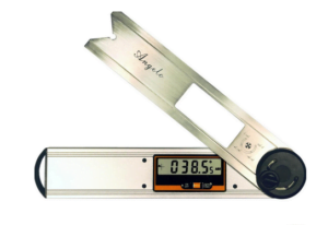
Take the familiar vernier calipers. We often say that the accuracy of the vernier caliper is 0.1mm, in fact, this statement is not correct, it should be said that the resolution of the vernier caliper is 0.1mm. That is, when the change in length is 0.1mm, Can our eyes see it, tell it apart. The accuracy of the vernier caliper, because the accuracy represents the difference between the measured value and the true value, the accuracy is related to many factors. For example, temperature causes thermal expansion and contraction, when we see a change of 0.1mm, the real may be 0.09mm, such as the caliper bending, or the caliper engraving line is not particularly uniform, will lead to poor accuracy, but the resolution is still 0.1mm. To improve the accuracy of the measurement, we must first improve the resolution of the measurement, if the resolution can not be distinguished, then the accuracy from where to start. Resolution is the limit of accuracy, improve the resolution at the same time to eliminate the impact of other factors on the accuracy, in order to effectively improve the final accuracy.

The angle sensor based on acceleration principle is illustrated in detail. It is the measurement of gravitational acceleration on the sensitive axis of the acceleration sensor into angle data, that is, the angle value and the acceleration value into a sine relationship.

The resolution of tilt sensors are also often referred to as sensitivity. It is mainly caused by the noise of the sensor. The noise equivalent angular change is called the angular resolution. Because the size of the noise is related to the frequency response, the higher the frequency response, the greater the noise. The resolution of the sensor can be improved effectively by taking effective measures to suppress the noise. After the resolution is improved, there is a chance to compensate for the adverse impact of other factors on the accuracy.

Resolution accuracy of vernier calipers

Other factors affecting the accuracy of tilt sensors

Of course, there are many factors that affect the accuracy of tilt sensors, in addition to the most important resolution, but also include:

Zero bias–depending on the characteristics of the core sensitive device itself, it means that the sensor in the absence of angle input (such as absolute horizontal plane), the sensor measurement output is not zero, the actual output angle value is zero bias.

Nonlinearity— can be corrected later, depending on the number of correction points. The more correction points, the better the nonlinearity.

Horizontal axis error— refers to the error caused by coupling to the output signal of the sensor when the sensor applies a certain acceleration perpendicular to its sensitive axis or tilts at a certain angle.

Input shaft non-alignment – refers to the installation deviation of the sensor in the actual installation process, which actually includes the input shaft non-alignment and vertical shaft non-alignment errors.

Sum up

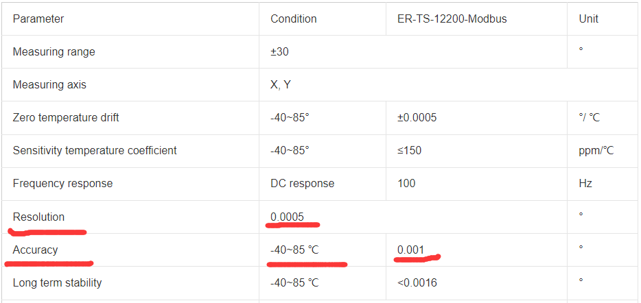
We use specific tilt sensors products to look at the relationship between resolution and accuracy, for example, our ER-TS-12200-Modbus, from the main parameters can be seen, its resolution is 0.0005°, that is, within the measurement range of ±30° can detect and distinguish the smallest change value measured is 0.0005°, the resolution is quite high. The comprehensive accuracy within the full temperature of -40~85° can reach 0.001°, because its resolution has been improved a lot, so its accuracy is naturally improved. 

Resolution and accuracy of High Precision Wireless Transmission Tilt Sensor

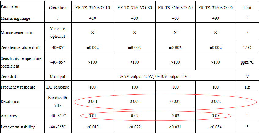
In the following figure, the main parameters of ER-TS-3160VO Low cost Voltage Type Single Axis Tilt Sensor, in different measurement ranges, its resolution is not the same, at ±10° its resolution can reach 0.001°, the accuracy is 0.01°. By comparing the parameters of these two products, we can see a relationship between resolution and accuracy. The resolution is low, the accuracy is relatively low, if the resolution is improved, the accuracy will be improved accordingly.

Resolution and accuracy of Low Cost Voltage Type Single Axis Tilt Sensor

High-precision IMU is coming to help in the fields of land, sea and air

  High-precision IMU is now widely used in many fields of sea, land and air. It can provide real-time and accurate information on the carrie...