Ericcogyro is a leader supplier of Inertial Sensor products North Finder,North seeking system,DTG,FOG,MEMS Gyroscope,Accelerometer,IMU,INS,electronic compass, our inertial sensor are sold worldwide and get the good feedback from our clients .
Inertial measurement units typically consist of three different types of sensors. The first type of sensor is an accelerometer, which measures acceleration, or the rate at which an object accelerates or decelerates. While there are many different sensor technologies for accelerometers, by far the most common for wearable applications is MEMS (microelectromechanical systems). MEMS are sensor systems composed of electrical and mechanical components, typically etched from micron-sized silicon.
Whenever the MEMS accelerometer experiences acceleration, the proof mass also experiences that acceleration. An etched spring set resists this acceleration. Using Hooke’s law (spring force is proportional to the distance the spring is compressed) and Newton’s second law (force is proportional to acceleration), check that the distance a mass moves is proportional to the acceleration it experiences (see figure below). This movement is sensed using the electrical properties of capacitance, which is related to the distance between two conductors. A set of electronics is then able to measure the change in capacitance, calibrate the signal, and further process it to give acceleration.
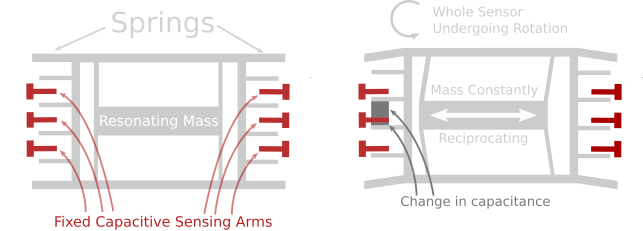
The second type of sensor in an Inertial measurement unitis a gyroscope, which measures angular velocity, or the speed and direction of an object’s rotation or spin. Gyroscopes also typically use MEMS technology, although they are more complex than MEMS accelerometers. The main physical phenomenon used in gyroscopes is the Coriolis effect, which describes the forces involved when an object moves in a rotating reference frame.
MEMS gyroscopes have masses that reciprocate at a constant frequency. During the rotation of the gyroscope, due to the Coriolis effect, the mass will induce a force perpendicular to the direction of the reciprocating motion. This force is counteracted by an etched spring and sensed by a capacitive sensing arm such as an accelerometer. Signal processing electronics then process the change in capacitance relative to the reciprocating motion of the resonant mass (see figure below).
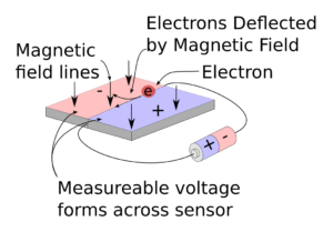
The final sensor commonly found in Inertial measurement units is a magnetometer, which measures the strength of a magnetic field and acts somewhat like a digital compass. Most magnetometers use the Hall effect to measure magnetic field strength. The basic premise of a magnetometer is that electrons moving in a conductor are deflected by the magnetic field to which the conductor is exposed. When charges pass through a conducting plate in a magnetic field, the magnetic field deflects the electrons to one side of the conducting plate. As more negative charge builds up on one side of the plate and more positive charge builds up on the other side of the plate, there is a measurable voltage between the two sides of the plate that is proportional to the strength of the magnetic field.
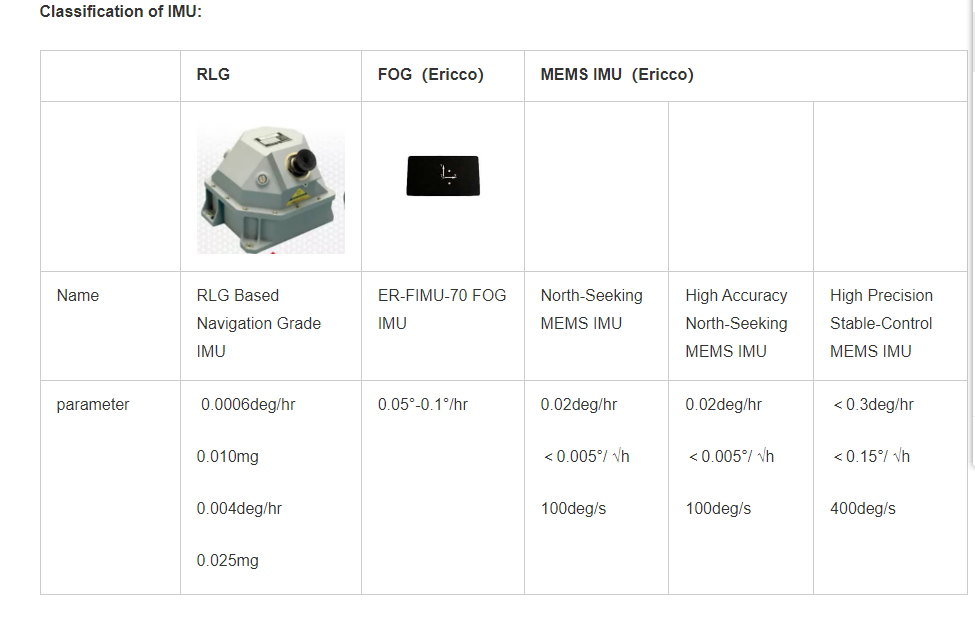
The current status and classification of IMU
Generally,Inertial measurement units on the market are divided into laser IMUs, fiber optic IMUs, and MEMS IMUs. Laser IMU has high cost, high precision, and large size. It is widely used in the military. It is a technology for positioning moving objects and guiding them to their destination safely, accurately, and economically. Fiber optic IMUs are medium in cost, large in size, and relatively medium in accuracy. MEMS generally refers to micron systems of 1um to 100um, or systems with outline dimensions on the millimeter level and component sizes on the order of microns. MEMS-IMU is an inertial measurement unit based on MEMS technology. It is divided into tactical grade and navigation grade, with low precision and small size. Several high-precision, small size, light weight, low cost, and high-performance MESM IMUs have recently appeared on the market. For example, Ericco’s newly developed tactical-grade ER-MIMU03 and ER-MIMU07 and navigation-grade ER-MIMU01 and ER-MIMU05 are small in size, light in weight, low in cost, high in performance, and use high-performance north seeking. Among them, the MEMS gyroscope (ER-MG2–100), can reach 0.1°/h. The accuracy is more accurate than the lowest-precision IMUs of many large companies, and can better reflect its high performance in complex environments.
This article explains how the Inertial measurement unit works and how it works. I hope you have a general understanding of IMU. If you want to know more information, you can find useful content in “More technical questions”. If you are interested in IMU related products, you can click “Products in Articles”.
If you want to buy imu, please contact our relevant personnel
Question 1: What is the resolution of atilt sensor?
A: It refers to the smallest change to be measured that can be detected and distinguished by the tilt sensor within the measurement range.
Question 2: What is precision?
A: Accuracy refers to the actual angle and tilt sensor measurement angle multiple times (>24 times) root mean square value error of the measurement.
Question 3: How can the sensor be installed to ensure its best accuracy?
A: During installation, the sensor mounting surface should be kept parallel to the target of the measured surface, and the influence of dynamic and acceleration on the sensor should be reduced. The product can be installed horizontally or vertically, and the vertical installation is suitable for single-axis tilt sensor, which is suitable for measuring range < The 60-degree product is installed horizontally, and the front of the sensor is marked with X and Y direction indication stickers, which can be referred to when installing.
Question4: What does offset mean in analog output sensors?
A: Zero bias voltage, if you customize the 0~5V output, then the zero position voltage output 2.5V.
Question 5: The larger the measurement range of the inclination sensor, does it determine the better and more expensive the product?
A: Can not be understood in this way, relatively speaking, the size of the range and the accuracy will be inversely proportional, the smaller the range, the higher the accuracy, the price is not directly related to the range.
Question 6: How can the visual value be less than the actual measured value (especially for the tilt alarm of the platform monitored by the tilt switch, the old-fashioned alarm)?
A: There may be an installation angle when the tilt switch is installed, and at this time, the tilt switch has an initial angle, so that the actual application will appear larger than the visual angle, and an alarm will occur.
Question 7: How can the visual angle of an electronic compass be greater than the measured angle?
Answer: Because the two axes of the inclination measurement are the most sensitive, when the inclination direction is not aligned with the measurement axis, the actual value will be greater than the measured value, which can also be understood as a projection.
Question 8: Which direction does the single-axis and dual-axis measurement of the tilt sensor refer to?
A: The double axis can measure the rollover (X direction) and pitch angle (Y direction), while the single axis can only measure the rollover angle or pitch angle when selecting the horizontal installation. If the single axis can only measure the rollover angle when selecting the vertical installation, the pitch angle is not optional.
Question 9: Do your products work well in harsh industrial environments?
A: At present, our products are used in various industrial control fields, including underground non-underground mining machinery, underwater machinery, Antarctic survey, oil drilling, etc., and the work is very stable.
Question 10: How to understand course accuracy?
A: The course accuracy refers to the root-mean-square error, not a random error, and to compensate for the influence of the surrounding static magnetic field, and the magnetic inclination should not be greater than 75 degrees of the value.
Question 11: In actual use, the electronic compass can not reach the nominal accuracy, especially in the measurement of the presence of pitch angle and roll angle.
A: Generally, the environment at the time of calibration is different from that at the time of use, so the calibration failure cannot guarantee the established indicators. If there is no tilt or roll in the rotation of the electronic compass during calibration, but there is a tilt and roll phenomenon in actual use, so this calibration is not effect.
Question 12: Axis alignment problem during installation of electronic compass?
A: The north point on the mounting surface of the electronic compass can be at a certain angle with the axis of the mounted body, which can be solidified into the memory body in the device through the setting software of the electronic compass for normal use to correct the output value.
A :1. In order to avoid strong magnetic interference, please be more than 0.5 meters away from the magnetic field source;
If there is magnetic field interference of other supporting products around the installation, it is recommended to calibrate the device before using it. For details about the calibration method, see the calibration instructions in the product manual or consult technical support.
In Summary:
Question 5 we mentioned above: Does the larger the measurement range of the tilt sensor determine the better and more expensive the product?
A: Can not be understood in this way, relatively speaking, the size of the range and the accuracy will be inversely proportional, the smaller the range, the higher the accuracy, the price is not directly related to the range.
Let’s take these two wireless tilt sensors as an example, the measuring range of ER-TS-12200-Modbus is ±30°, the measuring range is very small, but its accuracy reaches 0.001°. Small range but high precision.
We use this product ER-TS-32600-Modbusfor comparison. Its range is ±90°, which is larger than the above product, but its accuracy is only 0.01°. It can be seen that the range size and accuracy are indeed inversely proportional.
Customers in the use of the process may encounter some common problems, these problems are often consulted by customers in the past, in order to avoid causing unnecessary trouble to customers, Ericco listed here with the majority of customers and peers to share our experience.
Inertial Measurement Units (IMUs) are critical sensor systems in many applications, including navigation, robotics, motion science, and autonomous driving. The IMU consists of an accelerometer and a gyroscope, which are used to measure the acceleration and angular velocity of an object, thereby providing attitude and position information of the object. However, IMUs often have errors due to manufacturing and environmental factors, which affect their measurement accuracy. Therefore, the IMU needs to be calibrated to eliminate these errors. This paper proposes an IMU self-calibration method based on factorization. The method includes steps such as sensor calibration, initial alignment, data preprocessing, motion compensation, fusion algorithm, attitude solution and error correction. This method enables self-calibration without the use of external measurement equipment, greatly reducing the complexity and cost of calibration. 1. Sensor calibration Sensor calibration is the first step in the calibration process. The purpose is to determine the static parameters of each sensor in the IMU, such as sensitivity and bias. This step usually needs to be performed in a laboratory environment by applying known acceleration and angular velocity and comparing the sensor measurement results with the actual values to obtain the calibration parameters of the sensor. 2. Initial alignment Initial alignment is an important step in the calibration process, its purpose is to determine the initial attitude and position of the IMU. In this step, the IMU is fixed in a reference coordinate system with known position and attitude, and its measurement data is then recorded. By comparing these measured data with known reference data, the IMU's initial attitude and position information can be calculated.
3. Data preprocessing The purpose of data preprocessing is to remove noise and outliers to improve the accuracy of the calibration process. This may include filtering algorithms, such as Kalman filters or low-pass filters, to reduce the effects of noise. In addition, the identification and removal of outliers is also an important part of data preprocessing. 4. Motion compensation Motion compensation is an important step in the calibration process, aiming to improve the accuracy of the IMU by identifying and compensating for the dynamic effects of objects in motion. These effects may include the Earth's gravitational acceleration and the Coriolis force, among others. Methods to compensate for these effects often include using fusion algorithms to fuse IMU data with external sensor data such as GPS or magnetometers. 5. Fusion algorithm Fusion algorithm is the process of fusing multiple sensor data together to obtain more accurate attitude and position information. Common fusion algorithms include Kalman filter and extended Kalman filter. These algorithms can optimize the fusion of data based on the characteristics and accuracy of different sensors, thereby improving the measurement accuracy of the IMU. 6. Attitude calculation Attitude calculation is the process of calculating the attitude of an object based on the measurement data of the IMU. In this process, quaternions or rotation matrices are usually used to represent the attitude of the object. Attitude calculation methods include accelerometer- and gyroscope-based data fusion and the use of additional sensor data (such as magnetometers) for attitude correction. 7. Error correction Error correction is the process of eliminating or reducing IMU errors during calibration. These errors may include sensor sensitivity errors, bias errors, cross-coupling errors, etc. Error correction methods include self-calibration algorithms based on factorization and iterative optimization using known motion patterns. Through these methods, the measurement accuracy of the IMU can be significantly improved and the impact of errors can be reduced. Summarize The IMU self-calibration method based on factorization mainly includes the following steps: 1. Use the original data of IMU for error modeling; 2. Factorize the error model and identify error factors; 3. Correct the error factor through algorithm optimization or hardware compensation; 4. Use the corrected data to recalibrate the IMU to improve its measurement accuracy. Compared with other traditional IMU calibration methods, the factorization-based self-calibration method has the following advantages: 1. Multiple error factors can be automatically identified and corrected, while traditional methods can usually only calibrate a single error; 2. No additional calibration equipment or complex environmental settings are required, reducing calibration costs and time; 3. Calibration parameters can be dynamically adjusted according to actual conditions, improving the flexibility and accuracy of calibration. Domestic company ERICCO has been committed to the research of inertial products. For IMU, we not only have optical fiber IMU, but also MEMS IMU. We also have our own advantageous products: ER-MIMU01, ER-MIMU05, and ER-MIMU02, which have the characteristics of high precision, low power consumption, light weight, and small size. The most important thing is that the navigation-level one does not need a magnetometer and can find north independently. If you want to learn about or purchase IMU, please contact our relevant personnel.
An accelerometer is an instrument used to measure the linear acceleration of an object. It integrates the acceleration within a certain period of time to obtain the speed of the object under measurement, and integrates the speed to obtain the displacement of the object under measurement. The net acceleration or force of the system over time is gravity, and an accelerometer can also be used to measure the static Angle of tilt or tilt. The quartz flexible accelerometer is one of the representative products of the accelerometer, and adopts high-quality quartz crystal, which can realize high precision acceleration measurement, and has high reliability and stability. Its special flexible construction enables it to adapt to high acceleration applications under various environmental conditions, such as high temperature, high pressure and high vibration environments.
Applications in the aerospace field
Quartz vibration beam accelerometers can be used to measure the body vibration and flight state of aircraft in order to better estimate the life of aircraft and maintenance costs. In addition, the quartz vibration beam accelerometer can also be used in the development of pilot helmets to ensure that it can smoothly adapt to aerodynamic changes, and thus ensure the safety of the pilot. For example, ER-QA-03A has a zero-bias stability of 10-50μg, a scale factor repeatability of 15-50 PPM, and a second-order nonlinearity of 10-30μg/g2, which is often the best choice for high-performance, aerospace applications.
Applications in oil drilling
Quartz flexible accelerometer is one of the many accelerometers with relatively simple structure, high performance-to-volume ratio and performance-to-price ratio, especially in the high temperature environment of drilling and logging. It is one of the few accelerometers in China that has been verified by a lot of actual underground work experience, and has high temperature and high reliability product characteristics. The ER-QA-03D is designed for the drilling sector and is capable of shock resistance of 0.5ms at 500-1000g in an operating environment of -55 to 180 ° C.
If you want to know more about quartz accelerometers or purchase, please contact me through the following ways:
IMU is used to measure the angular velocity and acceleration of objects. The accuracy of the IMU determines the accuracy of its measurement data and has an important impact on the deception detection algorithm. Global navigation satellite system (GNSS)/inertial navigation system (INS) tightly integrated navigation system usually uses the original observation information (such as pseudorange, pseudorange rate, Doppler, etc.) output by GNSS as Measurements. INS is an inertial navigation system, a system that uses IMU measurement data for navigation. The optimal state estimator of the system is obtained through fusion filtering by the Kalman filter and the measurement values output by the inertial measurement unit in the INS. The tight combination mode has become a hot spot in the current research on GNSS/INS integrated navigation technology due to its moderate calculation amount and good navigation performance.
For civilian satellite navigation signals with an open signal system, forwarding deception and generative deception methods can be used; however, for authorization signals with unknown pseudo codes, forwarding deception and interference can be used, so the accuracy and security of navigation and positioning are seriously threatened. . Deception detection in integrated navigation systems is an important way to improve the reliability of integrated navigation systems. Among them, commonly used innovation-based deception detection methods include snapshot deception detection method and continuous deception detection method. It is difficult to detect ramp-type pseudorange spoofing using the snapshot spoofing detection method, but the detection effect for step-type spoofing is much better. The continuous spoofing detection method can effectively detect the slope spoofing problem, but the longer the window, the longer the calculation time.
The impact of different IMU accuracy on the tight combination anti-spoofing interference algorithm will be analyzed below. Firstly, the GNSS/INS tight combination model and spoofing interference model are explained. Secondly, the impact of the propagation error of IMUs with different performances on the pseudorange prediction value and the mean value of innovation detection amount under the short-time uniform linear error propagation model is analyzed. Finally, experiments were conducted to verify the impact of different precision INS on the tight combination deception detection algorithm.
1 GNSS/INS tight combination model and deception interference model
1.1 GNSS/INS compact combination model
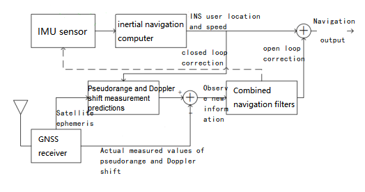
The GNSS/INS compact combination structure model is shown in Figure 1. Based on the receiver position velocity output by the INS and the satellite position velocity obtained from the GNSS satellite ephemeris, the combined system can more accurately predict the pseudorange and Doppler frequency shift of the GNSS signal, and these pseudoranges and pseudorange rates The difference between the predicted value and the actual GNSS measurement value forms the Kalman filter observation value. The observation value can be corrected for the INS positioning and speed results through the Kalman filter system.
Figure1 GNSS/INS tight combination diagram
In filters used with INS, the state vector is usually not the estimated state. In order to reduce the impact of linearization error, the error state vector is usually selected. According to the characteristics of the tight combination mode, a total of 17 states, including position error, velocity error, attitude error, gyroscope bias, accelerometer bias, clock error and clock drift, are selected as the error state vector. In closed-loop Kalman filtering, the error estimate obtained by filtering is fed back in each iteration to correct the system itself, making the Kalman filtering state tend to zero in the process. In open-loop Kalman filtering, since there is no feedback, the state value will gradually become larger as time goes by. Therefore, closed-loop Kalman filtering is commonly used in integrated navigation.
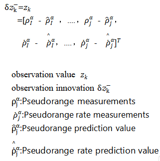
When performing closed-loop Kalman filtering, the observation value and the observation innovation are the same. Therefore, there are
1.2 Deception and interference model
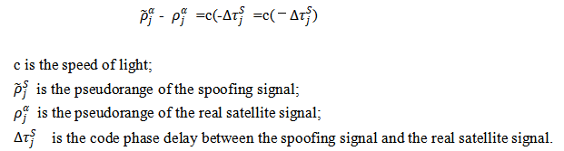
The mathematical model of pseudorange deception based on GNSS measurements can be expressed as
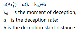
The code phase delay can be specifically expressed as
If a=0,b≠0, it means step pseudorange spoofing; if a≠0,b=0, it means slope pseudorange spoofing.
2 Impact of IMU accuracy on spoofing detection algorithm
2.1 Deception detection algorithm
The higher the accuracy of the IMU, the more accurate its measurement data, and the higher the accuracy of the deception detection algorithm. The accuracy of the IMU determines the response speed of the deception detection algorithm. For a Kalman filter, the measured innovation vector is shown in equation (4), which is the difference between the actual observation vector and the one-step prediction vector , that is
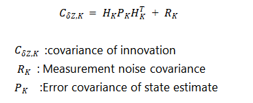
The innovation vector can indicate whether the measurement is consistent with the estimate, and its size is determined by the measurement error and the accuracy of the system model. When the accuracy of the system model is high, the Kalman filter information can represent the actual measurement error. The covariance of the innovation is the sum of the values converted into the measurement space by the measurement noise covariance and the error covariance of the state estimate, that is
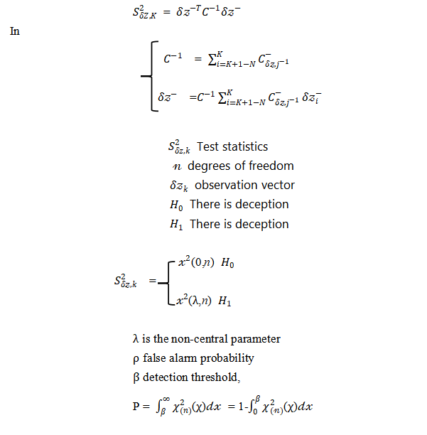
Smaller, slowly building up deviations between measurements and state estimates can be identified by a statistical test consisting of the latest N measurements. N is the “detection window”. When N is 1, it is snapshot deception detection, and when N is greater than 1, it is continuous deception detection. Chi-square test is often used in the innovation deception detection algorithm, and the innovation test statistic is constructed as
2.2 The impact of INS error propagation on observation information
IMU accuracy is usually characterized by bias and random noise. The bias error term exists in all accelerometers and gyroscopes. In most cases, the bias error term is the main component of all errors in inertial instruments; in addition, it is affected by a variety of Effect of Error Sources,All inertial sensors exhibit random noise.
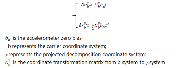
In the GNSS/INS combined system, since the output results of GNSS and INS must be fused and filtered every interval, when considering the impact of IMU accuracy on new information, the error propagation model of INS can be equivalent to a short-time uniform straight line Error propagation. The speed error is the integral of the acceleration error. The speed and position errors caused by the constant acceleration deviation are
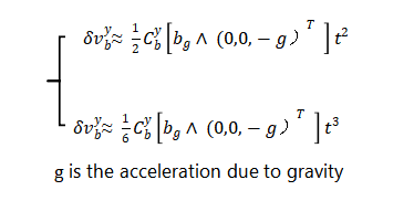
The measured specific force can be approximated as the opposite value of acceleration when moving at a uniform speed on a horizontal plane for a short period of time. Then the position and velocity errors caused by the gyro bias can be simply expressed as
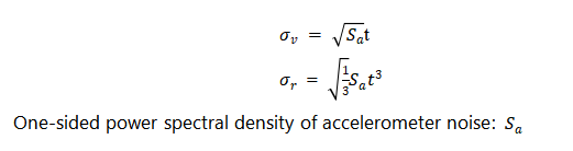
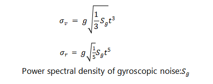
In the formula, is the acceleration due to gravity. In addition, in a well-designed system, the inertial sensor noise will be the largest noise source, which can be obtained from the inertial navigation error variance or the time update covariance matrix of the Kalman filter. In order to quantify the relationship between inertial navigation error and time, if the one-sided power spectral density of accelerometer noise is , then the standard deviation of the velocity error and position error caused by the noise is
In the same way, the standard deviation of the speed error and position error caused by noise is
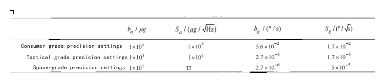
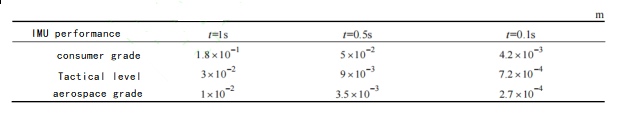
The IMU accuracy reference for different performance levels is shown in Table 1.
Table 1 IMU accuracy reference for different performance levels
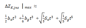
According to the IMU performance parameters shown in Table 1, calculate the pseudorange prediction error caused by INS error propagation at different state propagation intervals. Because the satellite velocity position at k can be obtained from the GNSS satellite ephemeris, assuming that the receiver position is accurately known, then The projection of the position error caused by the INS in the line of sight direction of the receiver and satellite is the pseudorange prediction value error. Consider the situation with the largest error, that is, we have
The calculation of propagation errors under different levels of IMU and different error propagation times is shown in Table 2.
Table 2 Pseudorange error
Therefore, the observation value error caused by the IMU accuracy not only increases as the IMU accuracy decreases, but also increases as the error propagation time increases. Since each iteration of the closed-loop Kalman filter corrects the system itself, the INS error propagation time in integrated navigation is the state propagation interval of the Kalman filter, that is, the observation value error caused by the IMU accuracy increases as the Kalman filter state propagation interval increases. And increase.
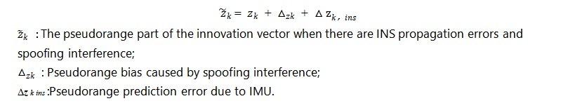
When using integrated navigation information to detect spoofing interference, it is usually assumed that the output of the INS within the state propagation interval is relatively accurate; however, due to the influence of IMU accuracy, the pseudorange error caused by the INS is close to or even exceeds that caused by spoofing interference at the same time. When the pseudorange deviates, the results obtained by innovation detection will become unreliable. It can be seen from the analysis in Section 1.1 that when there is an INS propagation error at time , the observation vector is also an observation innovation vector in the closed-loop correction, and the pseudorange observation part can be expressed as
The principle of innovation deception detection is to take advantage of the fact that innovation obeys a zero-mean Gaussian distribution when there is no deception interference, and obeys a Gaussian distribution with a non-zero mean when there is deception interference. However, if the pseudorange deviation caused by IMU accuracy is large, it will destroy the characteristics of the zero-mean distribution of innovations, thereby affecting the deception detection algorithm.
It can be seen that when using innovation for deception detection, there are requirements for IMU performance, that is, the total deviation of the observation value caused by the IMU within the detection window cannot exceed the detection threshold of the innovation deception detection algorithm.
3 Experiment and result analysis
3.1 Experimental design
In order to compare the impact of different IMU accuracy on deception detection algorithms, it is considered that the observation value error caused by IMU accuracy not only increases with the decrease of IMU accuracy, but also increases with the increase of Kalman filter state propagation interval and detection window length. Large, experiments are mainly designed from the following aspects:
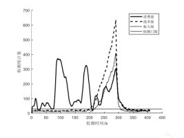
(Experiment 1) Apply the same ramp-type deception, and analyze and compare the impact of different precision INS on the deception detection algorithm within the same state propagation interval.
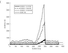
Figure 2 Detection situation at different IMU accuracy
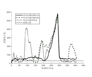
(Experiment 2) Apply the same ramp-type spoofing to analyze and compare the impact of lower-precision INS propagation intervals in different states on the spoofing detection algorithm.
Figure 3 Detection situation at different state propagation intervals
(Experiment 3) Apply the same ramp-type spoofing, and analyze and compare the effects of spoofing detection algorithms with different detection windows on low-precision INS and the same state propagation interval.
Figure 4 Detection conditions in different windows
Combining the results of the three experiments, it can be seen that IMU accuracy will indeed affect the detection effect of the deception detection algorithm. When using consumer-grade IMUs, the impact will be greater, and it may even cause the deception detection algorithm to fail. Specifically, when there is no interference from spoofing, the spoofing detection statistics are still affected by the error caused by the IMU accuracy, causing the spoofing detection statistics to exceed the threshold. And experiments show that the impact of low-precision IMU can be reduced by adjusting the Kalman filter state propagation interval and the detection window of the spoofing detection algorithm.
Summarize
Through theoretical derivation and simulation experiments, this paper comparatively analyzes the impact of different IMU accuracy on the tight combination anti-spoofing algorithm, and experimentally analyzes the effects of two factors: the Kalman filter state propagation interval and the detection window of the spoofing detection algorithm. The results show that the influence of different IMU accuracies on pseudorange estimates causes the innovation detection amount to no longer be zero mean when there is no spoofing interference. The use of innovation-based spoofing detection algorithms has requirements for IMU accuracy. With the detection probability and Kalman As the filtering state propagation interval increases, the requirements for IMU accuracy increase.
Specifically:
1) IMU accuracy does affect the detection effect of the deception detection algorithm, and consumer-grade IMUs can cause false alarms in the chi-square deception detection algorithm.
2) Under the condition that the state propagation interval of the Kalman filter is less than or equal to 0.1 s and the detection window used is equal to 1, the false alarm problem of the chi-square deception detection algorithm caused by the consumer-level IMU is solved, but when there is a detection greater than 50 s extension.
Then the domestic company ERICCO independently develops IMU, which is divided into navigation level and tactical level. Navigation-level ER-MIMU01 and ER-MIMU05 can independently seek north. Other IMUs only need to add GNSS and magnetometers to the IMU to independently seek north. They also have a wide range of applications. For example, ER-MIMU03 and ER-MIMU07 can be used in drones. This product has a built-in acceleration sensor and gyroscope, which can measure linear acceleration and rotational angular velocity in three directions, and obtain the carrier’s velocity through analysis. Attitude, velocity and displacement information enable precise positioning.
If you want to learn about or purchase IMU products, please contact our relevant personnel.
The precision of the quartz accelerometer is closely related to its processing and assembly accuracy during production. Accelerometer is a kind of instrument with complicated production process, and a large number of uncertain factors are introduced in processing and assembly. It is helpful to improve the accuracy of accelerometer by analyzing it in detail.
1) Processing technology
The components of quartz accelerometer have the characteristics of thin wall, high precision, complex shape and small size in structure. In the process of machining and assembly, the manufacturing accuracy, shape error and dimensional accuracy are all up to μm level. However, these parts will introduce some uncertain factors in the assembly process, so the whole process will inevitably introduce small errors. The structure of the accelerometer itself is relatively compact, and these small errors will inevitably affect the performance of the accelerometer.
Quartz crystal is the main component of quartz pendulum, it is a brittle non-metallic material, with high strength, high hardness, low conductivity and low fracture toughness characteristics. It is different from common metal materials, processing methods have a great impact on its strength, and any improper processing technology will affect the reliability, fracture strength and surface integrity of the quartz surface. At present, the commonly used processing method is laser cutting and chemical corrosion method, but this method has more procedures, and requires complex processes such as plugging, masking, and clamping. Experienced workers should also accurately grasp the corrosion time and acid temperature. Therefore, in order to improve the processing accuracy and efficiency, it is necessary to study the new processing technology.
2) Assembly technology
Assembly process quality directly determines the performance of the accelerometer. At present, the assembly process of the accelerometer is still using the traditional manual operation. The production acceleration timing adopts the assembly process of first trial assembly and then test. However, due to the large number of assembly links, it is difficult to accurately find the factors causing performance decline. Moreover, its performance is closely related to the operating habits, operating skills, experience knowledge, proficiency and other factors of assembly workers, resulting in the performance of the accelerometer after production being approximately normal distribution. The rate of special products is low. Therefore, in order to design a small-range and high-precision quartz flexible pendulum accelerometer and improve the overall performance of the accelerometer, it is necessary to consider the impact of processing and assembly technology on its performance, and scientifically improve the processing technology and assembly process of the accelerometer to reduce the manufacturing difficulty.
The quartz accelerometer ER-QA-03A produced by Ericco uses mature processing technology to ensure that it meets the demand for accuracy during use.
Railway transportation is one of the most important modes of transportation in China, and it has been developing continuously in recent years, with bullet trains, high-speed trains, intercity trains, and train speeds getting faster and faster. However, with greater speed comes greater danger, and accidents abound.
Although the state requires the limit of speed, but the limit of speed can not solve the fundamental problem, how to ensure driving safety, to create a stable and efficient driving environment is the most urgent need at present.
The train is a special means of transport running on the railway track. Its use environment is complex and changeable, and it is often affected by various factors such as wind, snow, earthquake, debris flow, landslide, tunnel foreign matter, geological mutation, etc. It is easy to cause deformation of the railway track and be covered by foreign matter, which seriously threatens the safety of the train.
Ericco’stilt sensor measurement accuracy of 0.01°, not only can accurately measure the inclination of the track, deformation, but also real-time monitoring of the inclination of the surrounding environment of the track, especially in some places rarely visited, in advance to make a preventive alarm, to avoid the occurrence of major accidents.