Wednesday, January 24, 2024

Application of Improved Wavelet De-noising Method in MEMS-IMU Signals

https://www.ericcointernational.com/application/application-of-improved-wavelet-de-noising-method-in-mems-imu-signals.html
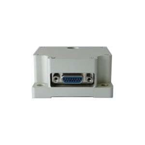
Application of High Accuracy North-Seeking MEMS IMU

IMU is an inertial measurement unit. Nowadays, MEMS IMU is widely chosen by consumers due to its advantages such as small size, high efficiency, and low cost. Therefore, the accuracy requirements for MEMS IMU will be relatively high. The main factors that can affect the accuracy of MEMS-IMU include Deterministic errors and random errors. Deterministic errors can be eliminated through calibration techniques; for random errors, Kalman filtering (KF) is usually used. However, KF requires a certain filtering model. The random error of MEMS-IMU is weakly nonlinear, non-stationary, and slowly time-varying, and is easily affected by uncertain factors such as the external environment. In this case, it is difficult to establish an accurate error model. At this time, using KF to deal with random errors will lead to low filtering accuracy and even filtering divergence.

Wavelet transform is a signal analysis method developed in the 1980s. Wavelet analysis is suitable for non-stationary signals, it can analyze local features, and can effectively reduce spike noise in non-stationary white noise. In addition, wavelet analysis does not require the establishment of a random error model, so it is very suitable for noise reduction processing of MEMS-IMU signals. The commonly used method for wavelet denoising is the wavelet threshold method, which can be traditionally divided into hard threshold method and soft threshold method. The hard threshold method can preserve the mutation signal well, but the hard threshold function is discontinuous at the threshold λj, which causes some oscillations when the signal is reconstructed using the estimated wavelet coefficients. The soft threshold method is continuous at the threshold λj, but there is a constant deviation λj between the estimated wavelet coefficients and those of the original signal, which results in blurred edges of the reconstructed signal and affects the accuracy of the reconstructed signal. If the improved threshold function has good continuity at the threshold λj, when the wavelet coefficients tend to infinity, the difference between the estimated wavelet coefficients and the original signal tends to zero. The original signal can be better preserved. However, the coefficient β in the improvement function is uncertain. To handle different signals, a large number of different betas need to be tested to adapt to the current signal, which results in poor flexibility.

In response to the above problems, this paper constructs a new wavelet threshold function without uncertainty coefficient, which makes up for the shortcomings of traditional soft and hard threshold functions and has better flexibility. It also shows that the improved wavelet threshold function can effectively reduce the noise of MEMS-IMU. This article will describe traditional wavelet threshold denoising, improved wavelet threshold function, and experimental results and analysis.

1.Traditional wavelet threshold denoising

The basic idea of wavelet threshold denoising was first proposed by Dohono of Stanford University. The algorithm is simple, requires little calculation, and is especially suitable for Gaussian white noise. The basic idea is as follows. Assume that the time signal sequence is:
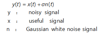
The noise signal is decomposed after wavelet transformation, and the wavelet coefficient value of the useful signal is greater than the wavelet coefficient value of the noise signal. Once appropriate thresholds are selected at different scales, wavelet coefficient values smaller than the predetermined threshold are directly reset to zero, while wavelet coefficient values larger than the predetermined threshold are retained or reduced. Then, the processed wavelet coefficient values are used to reconstruct the wavelet signal to suppress the noise. The main step of the wavelet denoising method is the process.

(1)Perform wavelet transform on the noise signal y. The basic formula is:

(2) Perform threshold processing on the wavelet coefficient d. Commonly used threshold functions include hard threshold functions and soft threshold functions. Perform threshold processing on wavelet coefficients. Commonly used threshold functions include hard threshold function and soft threshold function.

The hard threshold function can be described as:

The soft threshold function can be described as:

The function graphs of hard and soft threshold functions are shown in Figure 1 and Figure 2 respectively.
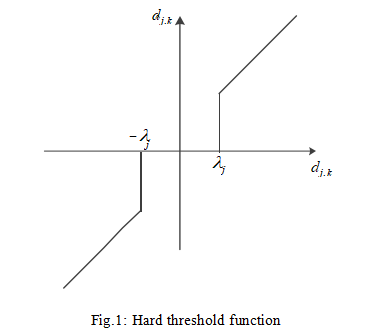
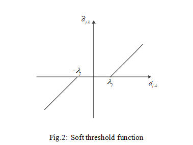
(3)Use the threshold-processed wavelet coefficient d to perform inverse wavelet transformation on the signal according to equation (2) to complete the wavelet reconstruction of the signal and obtain the denoised signal. Although the commonly used threshold function is simple and requires less calculation, it also has its shortcomings. The hard threshold function is discontinuous at A, so oscillations occur when the signal is reconstructed using the processed wavelet coefficients. Although the soft threshold function solves the discontinuity problem in hard threshold, there is always a constant deviation that affects the reconstruction accuracy.

2.Improved wavelet threshold function

In view of the shortcomings of the above soft and hard threshold functions, this paper constructs a new wavelet function. The improved wavelet threshold function can be recorded as:

The improved wavelet function image is shown in Figure 3.
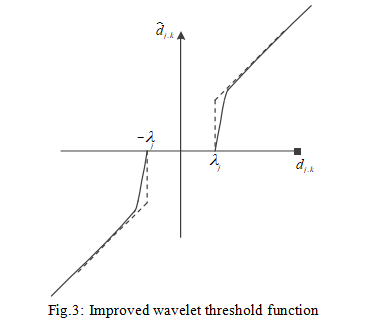
As can be seen from Figure 3, the improved wavelet function is continuous at the threshold, which makes the denoised signal after wavelet reconstruction have better smoothness and can retain the characteristics of the original signal. In addition, there is no uncertainty coefficient in equation (5), which is more flexible for denoising.

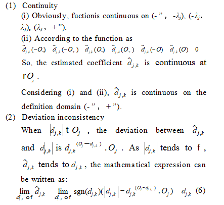
The continuity and deviation inconsistencies of the improved wavelet threshold function are proved as follows:
3.Experimental results and analysis

Through the MEMS-IMU measured data experiment, the denoising effect of the improved method on the MEMS-IMU output signal was verified.

The experimental conditions are as follows:

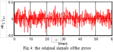
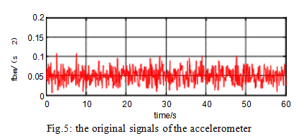
Set the MEMS-IMU to static and the gyroscope constant bias to 0.2. /h, gyroscope random white noise set to 10. /h standard deviation (SD). The accelerometer constant bias is set to 5u 10 to 3 g, and the accelerometer random white noise is set to 10 to 2 g SD. The output frequency is 10 Hz and the experimental time is 60 s.

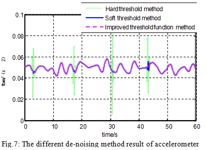
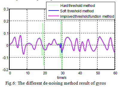
The raw signals from the gyroscope and accelerometer are shown in Figures 4 and 5. The denoising results of different methods for gyroscopes and accelerometers are shown in Figures 6 and 7.
Statistically rank the SD and denoised signals of the original signal for each method. The results are shown in the table below.
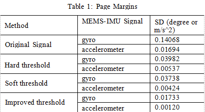
It can be seen from Figure 4 to Figure 7 and Table 1 that for the hard threshold denoising method, the reconstructed signal is easy to oscillate. For the soft threshold denoising method, the reconstructed signal accuracy is not high and the signal is not smooth. The improved wavelet threshold denoising method, the reconstructed signal is smooth, and the SD is smaller than the soft and hard thresholds, which fully demonstrates that the improved method has better denoising effect than the soft and hard thresholds.

Conclusion

The wavelet threshold function constructed in this paper overcomes the oscillation problem of the reconstructed signal caused by the discontinuity of the hard threshold function, and also solves the constant deviation problem of the soft threshold function. The noise in the signal is reduced and random errors in the MEMS-IMU signal can be effectively suppressed. So the company that is better at dealing with the signal error of MEMS IMU is ERICCO INERTIAL SYSTEM. As a company that develops inertial navigation products, ERICCO has independently developed MEMS IMU for many years, which can minimize the signal interference of MEMS IMU and improve the signal quality. Optimized for denoising. For example, ER-MIMU-01 and ER-MIMU-02, the accuracy of the gyroscope and accelerometer is relatively high compared to other companies. These two products are independently developed by ERICCO and are considered hot-selling products. If you want to buy MEMS IMU, please contact us.

Tuesday, January 23, 2024

Application of Tilt Sensor in Vehicle Four-wheel Positioning


Article details: https://www.ericcointernational.com/application/application-of-tilt-sensor-in-vehicle-four-wheel-positioning.html

Tilt sensor in the four-wheel locator

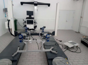
For different four-wheel positioning equipment, the key role is to measure the accuracy of the tilt sensor. Modern cars generally adopt front and rear independent suspension, and the main parameters detected by the four-wheel alignment instrument are wheel camber, kingpin rear angle, kingpin internal angle and front bundle. For the measurement of the above tilt angles, except the front beam angle is generally realized by the rotary disk or the angle sensor, and the other angles are generally adopted by the tilt sensor. The tilt sensor is fixed on the four-wheel alignment mounting plate, and then installed on the wheel of the car through the clamp.

Due to the reason of automobile structure, the tilt measurement of automobile wheel positioning angle is divided into direct measurement and indirect measurement. From the definition of wheel inclination, it can be seen that the measurement of wheel camber can be measured directly by the tilt sensor, while the kingpin internal inclination and kingpin rear inclination are not, because the kingpin is installed on the inside of the wheel, generally can not be measured directly by the tilt sensor. The measurement range of wheel inclination should be about ±15°. In today’s models, the inclination adjustment deviation value is generally about 5′, such as: Shanghai Volkswagen PASSAT B5 front wheel camber value is -0°35′ to ±0°25′, so the sensor measurement resolution should be less than or equal to 5′.

Application of Tilt Sensor in Vehicle Four-wheel Positioning

What is car four-wheel positioning?

From the structure of the car, the car’s steering wheel (front wheel), steering knuckle and front axle installation between the three has a certain relative position, this installation with a certain relative position is called steering wheel positioning, also known as front wheel positioning. Front wheel positioning includes

Kingpin back tilt (angle), kingpin inward tilt (angle), front wheel outward tilt (angle) and front wheel front bundle four contents. For the two rear wheels, there is also a relative position between the installation and the rear axle, called the rear wheel positioning. Rear wheel positioning includes wheel roll out (angle) and one rear wheel front bundle. In this way, the front wheel positioning and the rear wheel positioning are called four-wheel positioning.

When the vehicle leaves the factory, the positioning angle is pre-set according to the design requirements. These positioning angles are used together to ensure the driving comfort and safety of the vehicle. However, because the vehicle is sold and driven for a period of time, these positioning angles will change due to traffic accidents, severe bumps caused by uneven road potholes (especially when driving at high speed suddenly encounter uneven roads), chassis parts wear, chassis parts replacement, tire replacement and other reasons. Once the positioning angle changes due to any reason, it may produce uncomfortable symptoms such as abnormal tire wear, vehicle deviation, reduced safety, increased fuel consumption, accelerated wear of parts, heavy direction, and vehicle drift. Some symptoms make the vehicle very dangerous at high speeds.

Application of Tilt Sensor in Vehicle Four-wheel Positioning1

What is a four-wheel locator?

The purpose of four-wheel positioning maintenance service is to diagnose and treat the above causes of vehicle discomfort by measuring the positioning Angle. Generally, the new car should be four-wheel positioning after 3 months of driving, and every 10,000 kilometers after driving, replacing the tire or shock absorber, and after the collision should be timely four-wheel positioning. The correct positioning of the wheel can ensure that the steering is flexible, the seat is comfortable, the straight line driving is maintained, the life of the tire is extended, and the vibration caused by the road is reduced.

At present, most of the instruments used for wheel positioning detection are “four-wheel positioning instrument”. During the detection, the four-wheel positioning instrument first measures the current four-wheel positioning parameters of the car, and then the computer automatically compares it with the stored value of the corresponding model to calculate the deviation value of the four-wheel positioning of the car, and the maintenance personnel can restore the original state by correcting the prompts of the positioning instrument.

In Summary:

Ericco introduces the ER-TS-4256DI1, a tilt sensor for automotive four-wheel aligners, which has multiple interfaces and can be easily embedded into user systems. It can resist external electromagnetic interference, adapt to the harsh industrial environment for long-term work, is the ideal choice for industrial automation control and platform attitude measurement. The main features are as follows:

Biaxial dip measurement (X and Y) 

Resolution less than 0.01°, accuracy 0.1°

Single PCB board, easy to embed into the user circuit system

Single power supply, digital signal (RS485) output

Built-in temperature sensor (digital SPI output)

Vibration resistance 3500g  

MEMS Accelerometer Installation Error Correction Method


 In order to further improve the accuracy of MEMS accelerometer, the measurement error of mems acceleration sensor must be reduced as much as possible. The measurement errors of it mainly include heating and noise errors, installation errors and non-orthogonal errors between axes. In order to such measurement errors, various errors must be compensated and corrected.

Methods for correction of heat and noise errors

When the MEMS accelerometer output is affected by heat and electronic noise, it can be said that the main influence of  mems acceleration sensor output performance is heat and electronic noise. Electronic noise is usually a high frequency signal, so a low pass filter is added to the output of MEMS accelerometer to filter out the error caused by high frequency noise. After sampling and quantization, the filtered signal enters the DSP processor, and then performs digital filtering. The mean value of the quantization noise introduced is zero and has the characteristics of uniform probability density and white power spectral density. Therefore, it is assumed that the output of MEMS is affected by an additive white noise independent of the sampled signal and unbiased. So, by averaging multiple samples of MEMS output over a long enough period of time, the standard deviation of noise can be greatly reduced. After filtering and mathematical processing, the errors introduced by heat and electronic noise can be minimized.

Installation error model

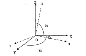
As shown in the figure, x, y and z axes are the coordinate system of MEMS acceleration sensor, and X, Y and Z axes are the measurement coordinate system. Due to the installation error of MEMS acceleration sensor during installation, there is a certain deviation between x, y and z axes of sensor coordinate system and the axis of measurement coordinate system. In order to change the performance of MEMS accelerometer and obtain accurate results, Therefore, the installation error should be compensated. Its mathematical model is as follows:

Installation error model of mems accelerometer

Taking the X-axis accelerometer as an example, when the sensor’s sensitive axis coincides with the X-axis of the measuring coordinate system:

Ax1=Ox+Sxx·Gx 

In the above formula:

Ax—X axis accelerometer’s output;

Ox—X axis accelerometer’s zero position error;

Sxx—X axis accelerometer’s scale factor ;

Gx—X axis gravitational acceleration component in the direction;

Taking the X-axis accelerometer as an example, when the sensor’s sensitive axis does not completely coincide with the X-axis of the measuring coordinate system, the Y-axis and Z-axis components will be generated, then there are:

Ax2=Sxy·Gy+Sxz·Gz

In the above formula:

Gy—y axis component of gravitational acceleration along

Gz—z axis component of gravitational acceleration along

Sxy—y axis correction coefficient of the gravitational acceleration component along

Sxz—z axis correction coefficient of the gravitational acceleration component in the direction

When these two cases are taken into account, a mathematical model of the accelerometer’s X-axis can be obtained:

Ax=Ax1+Ax2=Ox+Sxx·Gx+Sxy·Gy+Sxz·Gz

When extended to the case of three axes, the digital model of the three accelerometers on the probe is:

Digital model of mems acceleration sensor

Among them:

Output of Ax,Ay,Az – x,y,z accelerometers;

Gx,Gy,Gz – the true gravitational acceleration component in the x,y,z direction;

Oi,Si – Each correction factor (12 in total)

The traditional 6-parameter correction method only considers the zero error and scale factor of each axis, and does not consider the error between each axis, that is, Syx=Sxy=Szx=Sxz=Szy=Syz=0. Since the installation of the acceleration sensor will inevitably generate installation errors, the non-orthogonal error between each axis is not considered. Therefore, the measurement error of the 6-parameter correction method without considering the non-orthogonal error between the axes is relatively large.

MEMS accelerometer installation error correction method

According to the established mathematical model of the installation error of MEMS acceleration sensor, there are two methods to calculate the 12 parameters in the formula. The first method is the special point method, which uses the special position of the measurement coordinate system to calculate and separate the coefficients O,S, and then the real acceleration component G of each axis can be obtained. This method has high accuracy requirements for the measurement equipment,so the correction costs are high; Another method is the automatic calibration method, which has the advantage of increasing the measurement accuracy without being affected by the environment and equipment accuracy. Its theoretical basis is: under static conditions, the output vector of the MEMS acceleration sensor is consistent with the acceleration of the earth’s gravity. In a short time, the value of each parameter can be calculated by nonlinear optimization.

Principle of special point correction method

The method of special point correction is to put the MEMS acceleration sensor to be corrected in some special position by using the calibration table with high precision, so as to eliminate the coefficients in the model and calculate the parameters in the model.

Summary

The installation error analysis and correction of MEMS accelerometer is one of the important links, which can improve the accuracy and accuracy of the accelerometer. Of course, the choice of mems accelerometer is also a key link, ericco launched ER-MA-5 in zero bias stability can reach 5 μg, but also has the characteristics of small volume and light weight. It is believed that mems accelerometers with good cost performance and correct error correction methods will provide more stable and reliable data support for applications in related fields.

The full text link: https://www.ericcointernational.com/application/mems-accelerometer-installation-error-correction-method.html

Email : info@ericcointernational.com

Whats app:+8613992884879


Influence of Ambient Temperature on Measurement Data of Tilt Sensor


For the full article, click here https://www.ericcointernational.com/application/influence-of-ambient-temperature-on-measurement-data-of-tilt-sensor.html

1. How to reduce the impact of ambient temperature on the tilt sensor?

At present, the tilt sensor is widely used to measure the inclination Angle of various structures, such as foundation pit, slope, dam, railway system, etc., which can reflect the stability and safety of the structure. Temperature will affect the inclinometer sensor, which is the cause of the fluctuation of the measurement data of the inclinometer sensor. At present, the influence of ambient temperature on the measurement of the tilt sensor can be reduced by improving the hardware of the inclination sensor, such as changing the temperature of the heat source inside the sensor, adding the temperature compensation circuit, etc., but this method is more expensive and less accurate than the method that considers the relationship between the measurement data and the change of ambient temperature to establish the temperature compensation formula. Moreover, most of the measurements of inclination sensors are tested in the laboratory, and the sensor with temperature compensation function is redesigned according to the measurement results in the laboratory, which is different from the application of inclination sensors in practical engineering. Therefore, we analyze the inclination sensor data measured in the actual engineering environment, and establish the temperature compensation formula with appropriate fitting method, so as to reduce the influence of ambient temperature on the inclination sensor measurement data.

2. Principle of influence of temperature on measurement data of inclination sensor
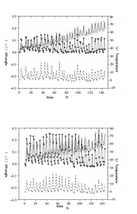
We set up an inclinometer sensor on a slope that needs to be monitored and use an automated monitoring platform to collect and receive sensor data in real time. We analyzed the original data of the inclination sensors extracted from July 15 to August 15, 2022, and the analytic results of part of the inclination sensors are shown in Figure 1.

tilt sensor data changes

As can be seen from Figure 1, the inclination of Angle X and Angle Y of the inclinometer sensor is significantly affected by temperature. The higher the ambient temperature is, the greater the data inclination Angle is. Moreover, Angle X is significantly affected by temperature than Angle Y, indicating that the ambient temperature has a greater impact on the output of the signal of the inclination sensor. The inclination sensor has a large temperature fluctuation error due to the change of ambient temperature in practical application. This is because under the influence of temperature, there will be some changes in the parameters of the devices in the sensor, which will affect the measurement accuracy and reliability of the sensor. Therefore, it is necessary to consider the influence of ambient temperature on the data, and establish the temperature compensation formula according to the actual measurement data of the inclination sensor, so as to correct the measurement data of the inclination sensor.

3. Establishment of temperature compensation formula
First, the influence range of temperature should be determined. As can be seen from Figure 1, the X Angle of inclinometer sensors 01 and 02 basically has no deviation during the period from July 15, 2022 to August 15, 2022. The data measured by inclination sensors 03 and 04 are analyzed. Moreover, the relative offset of X Angle of each sensor is less than ±0.025° (indicating that the floating error caused by temperature is small). The results are shown in Table 1.

Tilt sensorTemperature range
0126~31
0226~30
0326~33
0426~30

As can be seen from the statistical data in Table 1, when the inclination sensor is at (28±2) ℃, it can be seen from Figure 1 that the inclination degree of the inclination sensor X Angle and Y Angle is significantly affected by temperature. The higher the ambient temperature is, the greater the data inclination Angle is, and the influence of temperature on X Angle is more obvious than that of Y Angle. It shows that the ambient temperature has a great influence on the output of the inclinometer sensor signal, and the inclination sensor has a great temperature fluctuation error in practical application due to the change of ambient temperature. This is because under the influence of temperature, there will be some changes in the parameters of the devices in the sensor, which will affect the measurement accuracy and reliability of the sensor. Therefore, it is necessary to consider the influence of ambient temperature on the data, and establish the temperature compensation formula according to the actual measurement data of the inclination sensor, so as to correct the measurement data of the inclinometer sensor.
Moreover, it can be seen from Figure 1 that there is a linear relationship between the influence of temperature on the output value of the inclination sensor signal, and the following linear temperature compensation formula can be established:

X1=X0-A×(T-28) (1)

Y1=Y0-A×(T-28) (2)

Where: X0 is the original output value of X Angle of the inclination sensor, (°); Y0 is the original output value of the Angle Y of the inclination sensor, (°); X1 is the tilt Angle of the corrected X Angle, (°); Y1 is the tilt Angle of the corrected Y Angle, (°); T is the ambient temperature value output by the inclinometer

sensor, (°); A is the temperature compensation coefficient; A×(T-28) is a ring
Output increment due to ambient temperature. The size of the temperature compensation coefficient A is constantly adjusted to obtain better compensation effect, and the proportional coefficient of the temperature compensation coefficient A of each inclination sensor is finally obtained, as shown in Table 2.

Tilt sensorThe scale coefficient of A
X AngleY Angle
010.0070.004
020.0130.008
030.0050.004
040.0100.004

4. Analysis of temperature compensation effect
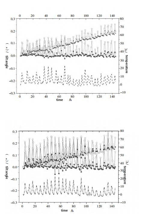
The results of X Angle and Y Angle corrected by the temperature compensation formula are shown in Figure 2. As can be seen from FIG. 2, the fluctuation of X Angle and Y Angle under the influence of temperature change after being corrected by the temperature compensation formula becomes significantly smaller. The variance of X Angle data of tilt sensor 01 is 0.001 950, and the modified variance is 0.000 169. The X-angle data variance of tilt sensor 02 is 0.00 648, and the corrected variance is 0.000 493. It can be seen from the above that the X and Y angles corrected by the temperature compensation formula are affected by the temperature change, and the fluctuations generated are reduced by one order of magnitude, indicating that equations (1) and (2) can effectively weaken the influence of ambient temperature on the measurement of the inclination sensor, improve the measurement accuracy of the inclination sensor, and meet the measurement needs of the actual environment.

Temperature compensation for the change in inclination

From the temperature difference of 1.5 ° C, 20 different grades of temperature are selected in the operating temperature range of the inclination sensor -20 ~ 70 ° C for testing. According to the annual temperature difference of about 30 ° C in Guangdong Province, the inclination sensor is put into the temperature control box. Starting from 5 ° C, the temperature difference interval of 1.5 ° C is heated. Keep heating up to 35 ° C and observe the data change. 7 different levels of pressure are selected from the range of -15° ~ 15° of the inclination sensor. Considering the basic level of the initial Angle when the inclination sensor is installed, the maximum installation inclination Angle does not exceed 10°, the cumulative variation given by the design unit of the project does not exceed 60 mm, and the maximum height of the slope is 10 m. According to the trigonometric function, the Angle is 0.35°, so the maximum Angle of the test is 12°. Then a test is performed every 4° from -12° to 12°, and the X and Y directions are involved in the test, with a total of 280 data. MATLAB software is selected to realize the verification and analysis of the model. The accuracy of the maximum relative error is verified by the formula as follows:

Error formula verification of tilt sensor


The results show that when the inclination is 10.5° and the temperature difference is 30 °, the error reaches 0.3°. After compensation, the maximum error is better than 0.01°; The maximum error before compensation is 12% and the maximum error after compensation is 0.15%. The compensation effect is good.

5 Summary
We study the influence of temperature on the measurement accuracy of the inclination sensor, and find that the inclination sensor has a large temperature fluctuation error due to the change of ambient temperature in practical application. In order to reduce the influence of the ambient temperature on the measurement accuracy of the inclination sensor, the temperature compensation formula is established based on the actual measurement data of the inclination sensor, and the relationship between the measurement data and the ambient temperature is fully considered. The main conclusions are as follows:
(1) The ambient temperature has a significant effect on the inclination sensor, and the higher the temperature, the greater the measurement error. Moreover, the temperature compensation coefficients of each inclination sensor are different, indicating that different inclination sensors are affected by temperature to different degrees.
(2) The error of X Angle and Y Angle measured by the inclination sensor is different under the influence of temperature, and the error of X Angle under the influence of temperature is larger than that of Y Angle. For example, ER-TS-12200-Modbus is a dual-axis monitoring system. In actual measurement, the error is different due to the influence of temperature. The error of X Angle due to the influence of temperature is larger than that of Y Angle.
(3) Considering the relationship between the measurement data and the change of ambient temperature, the temperature compensation formula is established and applied. The results show that the proposed temperature compensation formula can effectively reduce the influence of ambient temperature on the measurement accuracy of the inclination sensor.
Although it is greatly affected by the ambient temperature, such as our ER-TS-32600-Modbus and ER-TS-4250VO, temperature compensation formulas can be established to effectively correct and apply their measurement data, so as to reduce the impact of ambient temperature on the measurement accuracy of the sensor. 

Research on error modulation technology of MEMS based on IMU rotation


North-Seeking MEMS IMU

IMU(inertial measurement unit) is a sensor capable of measuring and outputting three axial accelerations and angular velocities. By combining a MEMS inertial device with an IMU, the error of the MEMS device can be modulated. This technology is mainly based on the principle of rotational modulation, changing the output signal of the MEMS device by rotating the IMU, thereby achieving error compensation and modulation. With the rapid development of microelectromechanical systems (MEMS) technology, MEMS inertial devices have been widely used in many fields. However, the error sources and effects of MEMS inertial devices are still a problem that needs attention and resolution. Among them, low signal-to-noise ratio and drift are the main factors affecting its application range. Therefore, it is of great significance to carry out research on error modulation technology of MEMS devices based on IMU rotation. The following is mainly introduced in three parts. They are: wavelet noise reduction, low signal-to-noise ratio and drift, and MEMS device error modulation technology based on IMU rotation.

1.MEMS wavelet noise reduction

Wavelet analysis is a rapidly developing new field in current applied mathematics and engineering disciplines. After years of exploration and research, an important mathematical formal system has been established, and the theoretical foundation has become more solid. Compared with Fourier transform, wavelet transform is a local transformation of space (time) and frequency, so it can effectively extract information from signals. Multi-scale detailed analysis of functions or signals can be performed through operation functions such as scaling and translation, which solves many difficult problems that cannot be solved by Fourier transform.

Noise reduction is one of the main uses of wavelet analysis in the field of signal processing. Denoising a signal actually suppresses the noise in the signal.

Use part to enhance the useful part of the signal process. The denoising process of the inertial device output signal is as follows: 3 steps:

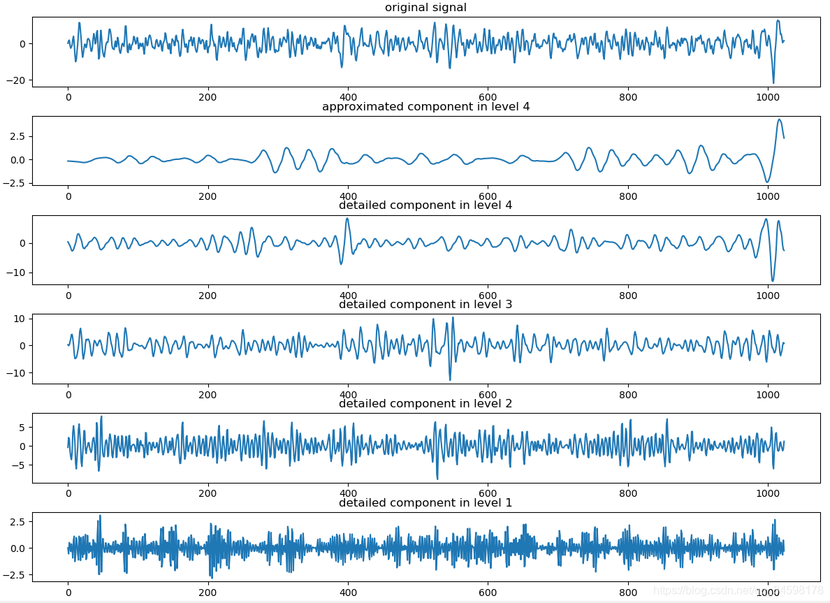
Step 1: Wavelet decomposition of the signal. Refer to Figure 1. Select an appropriate wavelet and determine the level of decomposition, and then perform decomposition calculations.

                                                                   Figure 1 Wavelet decomposition of signal

Step 2: Threshold quantization of high-frequency coefficients of wavelet decomposition. Select a threshold value for the high-frequency coefficients at each decomposition scale to perform soft threshold quantization processing.

Step 3: Wavelet reconstruction. One-dimensional wavelet reconstruction is performed based on the low-frequency coefficients of the lowest layer of wavelet decomposition and the high-frequency coefficients of each layer of decomposition.

Among these three steps, the most critical is how to select the threshold and perform threshold quantification processing. To some extent, it is related to the quality of signal denoising.

The wavelet basis function is determined based on the characteristics of the signal to be processed. The ideal wavelet basis should have the following properties:

1) Linear phase characteristics, which can reduce or eliminate the distortion of the reconstructed signal at the edges;

2) Compact support characteristics. The shorter the support, the lower the computational complexity of the wavelet transform, making it easier to implement quickly;

3) The evanescent moment characteristic determines the degree to which energy is concentrated in low-frequency components after wavelet transformation.

The Daubechies wavelet selected in this paper is a compactly supported orthogonal wavelet that has an extreme phase and the highest vanishing moment for a given support width. A related scale filter is the minimum phase filter. Theoretically, as the scale increases, the filtering effect will be better, but at the same time the amount of calculation will increase, and the calculation rounding error will also increase. Therefore, in practical applications, the accuracy requirements and calculation amount should be considered comprehensively. Determine the transform scale of the required wavelet. In addition, even if the carrier is in a static base environment, due to the influence of various external factors, certain external dynamic interference will be introduced into the output of the gyroscope and accelerometer, and the dynamic interference from the base will be introduced into the test output of the gyroscope. . Relative to the useful signal, these disturbances are high-frequency random interference. Therefore, wavelet transform can be used for filtering, which will effectively reduce the interference of disturbance and device noise.

2.Low signal-to-noise ratio and drift

Low signal-to-noise ratio and drift are the main factors affecting the errors of MEMS inertial devices, which are mainly reflected in the following aspects:

2.1 Signal interference and noise: MEMS inertial devices will be interfered by various external factors during operation, such as electromagnetic noise, thermal noise, etc. These interferences will cause the signal-to-noise ratio of the signal to be reduced. Low signal-to-noise ratio will affect the measurement accuracy and stability of MEMS inertial devices.

2.2 Stability of the output signal: Drift refers to the stability problem of the output signal of the MEMS inertial device. Due to the physical characteristics of MEMS devices, their output signals may change with time, temperature and other factors, resulting in measurement errors.

2.3 Analysis of error sources: Low signal-to-noise ratio and drift are mainly caused by problems in the design, manufacturing and packaging of MEMS inertial devices. For example, defects introduced during the manufacturing process, stress during packaging, temperature changes, etc. may cause changes in the output signal of the MEMS inertial device.

2.4 Algorithm and data processing: In practical applications, algorithms and data processing technology are needed to reduce the impact of low signal-to-noise ratio and drift on MEMS inertial devices. For example, filters, compensation algorithms, etc. can be used to improve the measurement accuracy and stability of MEMS inertial devices.

2.5. Testing and verification: In order to evaluate the impact of low signal-to-noise ratio and drift on MEMS inertial devices, sufficient testing and verification are required. By building an experimental platform and conducting comparative experiments, the performance of MEMS inertial devices can be objectively evaluated.

In summary, low signal-to-noise ratio and drift are the main factors affecting the errors of MEMS inertial devices. They need to be reduced by in-depth analysis of their causes, the use of effective algorithms and data processing technology, and sufficient testing and verification. Impact on MEMS inertial devices.

3.MEMS device error modulation technology based on IMUrotation

In the MEMS device error modulation technology based on IMU rotation, the MEMS output information first needs to be preprocessed. Since there are random noise signals in the output signals of MEMS devices, these noise signals will adversely affect the measurement accuracy and stability of MEMS devices. Therefore, effective noise reduction technology needs to be used to process MEMS output information. Wavelet noise reduction technology is an effective signal processing method, which can effectively eliminate random noise signals and improve the device output signal-to-noise ratio. By applying wavelet noise reduction technology to MEMS output information, effective modulation of MEMS device errors can be achieved.

During the error modulation process, it is necessary to analyze the error modulation principle under the IMU rotation scheme. The rotation of the IMU can change the output signal of the MEMS device. Through a reasonable rotation scheme, effective compensation and modulation of the MEMS device error can be achieved. To achieve this goal, the rotational modulation scheme needs to be optimized and designed. The optimization goal can be to improve the measurement accuracy, stability, reliability, etc. of MEMS devices.

Furthermore, the engineering feasibility of rotational modulation needs to be explored. In practical applications, the rotation modulation scheme needs to take into account the actual application environment and conditions, such as rotation angle, rotation speed, rotation method, etc. These factors will all have an impact on the implementation of rotational modulation. Therefore, these factors need to be comprehensively considered and optimized to ensure the feasibility and effectiveness of rotational modulation.

In order to verify the effectiveness of the MEMS device error modulation technology based on IMU rotation, a MEMS rotation experimental environment can be built and experimental research can be carried out. MEMS devices of different types and specifications can be tested and analyzed in the experiment to evaluate the applicability and effect of the technology. At the same time, it can also be compared and analyzed with other error compensation technologies to further verify the advantages and potential of this technology.

Summarize

In short, the research on MEMS device error modulation technology based on IMU rotation is of great significance and application value. Through the research and application of this technology, the measurement accuracy, stability and reliability of MEMS inertial devices can be effectively improved, and the application and development of MEMS technology in various fields can be further promoted. The low signal-to-noise ratio and large drift of existing MEMS inertial devices have become technical bottlenecks that make it difficult to achieve rapid improvement in a short period of time. This paper uses the idea of averaging technology in signal processing to propose a MEMS device error modulation method based on IMU rotation and implements wavelet analysis to complete inertial device noise reduction processing under the IMU rotation state. ERICCO is a company specializing in the research and development of inertial navigation products. The independently developed MEMS IMU is trusted by consumers across the country. MEMS IMU can achieve light weight, small size, high performance, and can greatly save installation space, reduce carrier load, and reduce user expenses. For example, the navigation-level ER-MIMU-01 can independently seek north. The gyroscope included in the product has relatively high accuracy. Compared with other inertial navigation companies, it is relatively friendly to consumers.

If you want to know more about IMU, please contact our relevant technical personnel.

https://www.ericcointernational.com/application/research-on-error-modulation-technology-of-mems-based-on-imu-rotation.html

High-precision IMU is coming to help in the fields of land, sea and air

  High-precision IMU is now widely used in many fields of sea, land and air. It can provide real-time and accurate information on the carrie...