Ericcogyro is a leader supplier of Inertial Sensor products North Finder,North seeking system,DTG,FOG,MEMS Gyroscope,Accelerometer,IMU,INS,electronic compass, our inertial sensor are sold worldwide and get the good feedback from our clients .
Thursday, February 1, 2024
ZigBee technology wireless transmission inclinometer sensor
ER-TS-12200-Modbus Features:
1. Dual axis monitoring (single axis optional);2. Full range accuracy 0.001°, resolution 0.0005°;
3. Volume (94*74*64mm) (customizable).
Introduction
ER-TS-12200-Modbus High Precision Wireless Transmission Tilt Sensor is a wireless inclination sensor with ultra-low power consumption, small size and high performance, which is aimed at the industrial application of users without power supply or real-time dynamic measurement of object attitude angle. Powered by lithium battery, based on Internet of things technology Bluetooth and ZigBee (optional) wireless transmission technology, all internal circuits have been optimized and designed, and various measures such as industrial MCU, three proof PCB board, imported cable, wide temperature metal shell are adopted to improve the industrial level of the product. With good long-term stability and small zero drift, it can automatically enter the low-power sleep mode, so as to get rid of the dependence on the use environment.
The product has compact structure, precise design, recompensation for temperature and linearity, and integrated comprehensive protection functions such as short circuit, instantaneous high voltage, polarity, surge, etc. it is simple and convenient to use. The wireless digital signal transmission method eliminates the cumbersome wiring and noise interference caused by long cable transmission; The industrial design has extremely high measurement accuracy and anti-interference ability. The wireless sensor nodes can form a huge wireless network, support thousands of measuring points to monitor the inclination at the same time, and support professional computer software. Without field survey, it can measure and record the state of the measured object in real time; The safety monitoring system is suitable for remote real-time monitoring and analysis of industrial sites, dilapidated houses, ancient buildings, civil engineering, tilt deformation of various towers and other needs.
Features
Dual axis monitoring (single axis optional)
Range: ±30°
Accuracy: 0.001°, resolution: 0.0005°
Volume (94*74*64mm) (customizable)
Ultra low power consumption
Powered by built-in rechargeable lithium battery
Wide temperature operation -40~+85℃
IP67 protection grade
Applications
Bridge construction
PTZ levelling
Ship navigation attitude measurement
High railway foundation tunnel monitoring
Satellite solar antenna positioning
Medical equipment
Angle control of various construction machinery
Wednesday, January 31, 2024
Calibration method and error analysis of low-precision MEMS IMU
MEMS IMU, Micro Electro-Mechanical System Inertial Measurement Unit, low-precision MEMS IMU is a sensor module that integrates a micro accelerometer and a micro gyroscope. It is mainly used to measure the acceleration and angular velocity changes of objects in three axes. This kind of sensor is mainly used in fields such as attitude angle measurement, motion status monitoring, navigation and positioning. Compared with high-precision MEMS IMU, low-precision MEMS IMU has lower accuracy, but has the characteristics of small size, light weight, and low power consumption. It is suitable for application scenarios with low accuracy requirements and limited cost.
The accelerometers of low-precision MEMS IMUs are generally produced using micromachining technology and have the advantages of wide measurement range, high resolution, and good reliability. The gyroscope is implemented using vibration or optical principles, which has the advantages of fast startup speed and high measurement accuracy. In a low-precision MEMS IMU, the accelerometer and gyroscope perform data fusion and combine the initial position and velocity information to calculate the object’s current position and attitude.
In practical applications, low-precision MEMS IMU needs to be used in conjunction with other sensors, such as GPS, barometer, magnetometer, etc., to improve the accuracy and stability of navigation and positioning. At the same time, low-precision MEMS IMU also requires necessary calibration and calibration to reduce the impact of various error sources and improve the accuracy and reliability of measurements.
This article will introduce the calibration process, error sources and analysis of MEMS IMU.
1.Calibration process
The calibration process of low-precision MEMS IMU mainly includes the following steps:
1.1 Static calibration
Static calibration is an important part of the low-precision MEMS IMU calibration method. Its main purpose is to eliminate the offset error of the IMU and improve its measurement accuracy in a static environment. During the static calibration process, the IMU needs to be placed in a static state, raw data in all directions is collected, and the calibration algorithm is used to estimate the parameters of the accelerometer and gyroscope. The static calibration method is relatively simple, but it is necessary to ensure the stability and temperature consistency of the IMU to reduce the impact of the external environment on the calibration results.

IMU calibration
1.2 Dynamic calibration
Dynamic calibration is another important link in the low-precision MEMS IMU calibration method. Its main purpose is to eliminate the sensitivity error and cross-coupling error of the IMU and improve its measurement accuracy in a dynamic environment. During the dynamic calibration process, dynamic excitation needs to be applied to the IMU, raw data in all directions is collected, and the parameters of the accelerometer and gyroscope are estimated using the calibration algorithm. The dynamic calibration method is relatively complex and requires the use of additional excitation equipment and precise control of factors such as frequency, amplitude, and phase of the excitation signal.
1.3 Data collection and processing
Data acquisition and processing are the basic links in the low-precision MEMS IMU calibration method. Its main task is to collect the original data of the IMU and perform necessary preprocessing and feature extraction. During the data collection process, it is necessary to ensure the accuracy and reliability of the data and avoid interference from electromagnetic interference, noise and other factors. During the data processing process, the original data needs to be filtered, smoothed, denoised, etc. to extract useful feature information to facilitate subsequent parameter estimation and model establishment.
1.4 Error model establishment
Error model establishment is the core link in the low-precision MEMS IMU calibration method. Its main task is to establish an error model based on the collected raw data and known calibration parameters to describe the measurement error of the IMU. In the process of establishing an error model, it is necessary to select appropriate mathematical models and algorithms, consider the impact of various error sources, and use a large amount of data to train and optimize the model. The established error model can be used for subsequent parameter optimization and accuracy verification.
1.5 Parameter optimization
Parameter optimization is a key link in the low-precision MEMS IMU calibration method. Its main task is to continuously optimize the calibration parameters through iteration and reduce the measurement error of the IMU. During the parameter optimization process, it is necessary to select an appropriate optimization algorithm and objective function, and use an error model to guide the optimization process. Optimized parameters usually include accelerometer and gyroscope bias, sensitivity, cross-coupling and other parameters. Through parameter optimization, the measurement accuracy and stability of the IMU can be improved to better meet the needs of practical applications.
1.6 Accuracy Verification
Accuracy verification is a necessary part of the low-precision MEMS IMU calibration method. Its main task is to evaluate the measurement accuracy of the calibrated IMU by comparing actual measurement data with known standard data. During the accuracy verification process, it is necessary to select representative test samples and use the error model to predict and evaluate the test samples. At the same time, the test results need to be compared with the uncalibrated IMU to verify the effectiveness and superiority of the calibration method. The results of accuracy verification can be used as an important basis for evaluating the performance of the calibration method.
1.7 Repeatability Test
Repeatability testing is an important part of the low-precision MEMS IMU calibration method. Its main task is to evaluate the stability and reliability of the IMU performance by conducting repeatability tests at different times and in different environments. During the repeatability test process, it is necessary to maintain the consistency of the test conditions and perform statistical analysis on the test results. By comparing the differences and trends between different test results, the performance and reliability of the IMU under different conditions can be evaluated. At the same time, the results of the repeatability test can also be used as an important basis for evaluating the performance of the calibration method.
2.Error sources and analysis
MEMS IMU errors are of great significance to improving its measurement accuracy and stability. The errors of low-precision MEMS IMU mainly come from bias error, sensitivity error, cross-coupling error, temperature error and repeatability error. The error analysis is as follows
1.Offset error:During long-term use, the accelerometer and gyroscope of MEMS IMU will have offset errors due to factors such as manufacturing processes and materials. Offset errors can cause the IMU to produce measurement errors in its stationary state. In order to reduce the offset error, long-term static calibration is required and the output of the accelerometer and gyroscope are filtered.
2.Sensitivity error:The sensitivity of the MEMS IMU’s accelerometer and gyroscope will be affected by factors such as manufacturing processes and materials, resulting in errors. Sensitivity errors can lead to inaccurate IMU measurements in dynamic environments. In order to reduce the sensitivity error, dynamic calibration is required and the output of the accelerometer and gyroscope are corrected.
3.Cross-coupling error: Cross-coupling error will occur between the accelerometer and gyroscope of the MEMS IMU, especially during high-speed rotation or vibration. Cross-coupling errors can lead to inaccurate IMU measurements in dynamic environments. In order to reduce cross-coupling errors, the physical design and circuit parameters of the IMU need to be optimized, and the outputs of the accelerometer and gyroscope need to be coupled and compensated.
4.Temperature error: The performance of MEMS IMU is greatly affected by temperature, and temperature drift will cause the measurement accuracy of the IMU to decrease. In order to reduce the temperature error, temperature compensation is required and devices with lower temperature drift are selected. At the same time, materials with good thermal stability can be used in the IMU package to reduce the impact of temperature on the performance of the IMU.
5.Repeatability error:The repeatability error of MEMS IMU refers to the error caused when the same parameter is measured multiple times under the same conditions. Repeatability errors are mainly affected by factors such as manufacturing processes and materials, and can be reduced by improving manufacturing processes and material quality. At the same time, filtering algorithms and statistical methods can be used to smooth the output of the IMU to reduce the impact of random noise and accidental errors.
In short, MEMS IMU error analysis is an important means to improve its measurement accuracy and stability. By analyzing and controlling various error sources, the errors of MEMS IMU can be effectively reduced and its performance improved.
Summarize
The above article describes the calibration method, error sources and error analysis of low-precision MEMS IMU. The output of MEMS IMU will also have deviations, and the calibration coefficients will also have deviations. Therefore, it is necessary to accurately calibrate the error coefficient of the MEMS IMU to improve the calibration accuracy.
As a developer and manufacturer of MEMS IMUs, Ericco has adopted strict control measures for the calibration methods of MEMS IMUs, especially the navigation grade ER-MIMU-01 and ER-MIMU-02 with excellent accuracy and high calibration accuracy. Among them, the gyro accuracy is relatively high, and the bias instability can reach 0.01-0.02°/hr and 0.03-0.05°/hr respectively.
If you are interested in other knowledge about MEMSIMU, please click the link below to learn more.
Tuesday, January 30, 2024
How to Improve Reliability of Tilt Sensors
1. How to ensure the reliability index of the tilt sensor
For the technical indicators and performance indicators of the tilt sensor, there are usually clear and quantitative index requirements, which can be directly measured and tested when the product leaves the factory. For reliability indicators, it is generally impossible to implement direct measurement and inspection, and it is necessary to carry out reliability design and control of the whole process of product development and production to ensure that the reliability indicators meet the requirements. We mainly discuss the reliability supervision and control, design and evaluation and test of tilt sensor in the development, production and use stage.
2. Reliability design
The development stage of inclinometer sensor can be divided into demonstration stage, scheme stage, development stage and finalize stage. According to the technical requirements of the tilt sensor, the MTBF task value θS of the sensor is determined in the demonstration stage, and the θS is preliminarily demonstrated according to the reliability level of the sensor product.
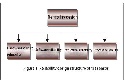
When the inclinometer sensor is in the project stage, it is necessary to design according to the tactical technical index of the inclination sensor and work out the functional block diagram of the sensor. According to the block diagram of tilt sensor, the internal logic relationship in the block diagram is analyzed, and the reliability block diagram of the newly developed inclination sensor is compiled. According to the reliability block diagram of the inclinometer sensor, the reliability indicators are assigned to each subsystem of the sensor, or the reliability indicators on the technical requirements are weighted, and the results after allocation must meet the reliability indicators of the whole system. After the reliability block diagram is prepared and the reliability index is assigned, the estimated reliability value θP is estimated for the components used in the hardware circuit. According to the obtained θP value, the part of the hardware circuit that affects the reliability of the sensor is designed and changed. At last, the functional block diagram, reliability block diagram, reliability distribution index and reliability predicted results prepared according to the technical requirements of the inclination sensor are reviewed periodically in order to improve the design of the defects that affect the reliability of the sensor. In the reliability design of the tilt sensor, the design needs to be considered as shown in Figure 1.

2.1 Reliability design of hardware circuit
After the inclinometer sensor enters the development stage, the hardware circuit is designed according to the functional block diagram and reliability block diagram.
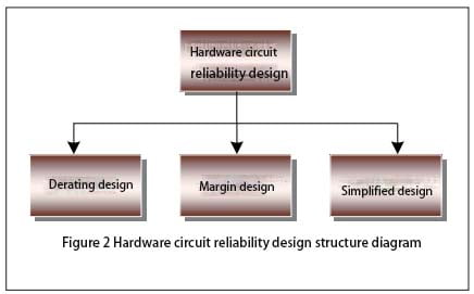
In the design of hardware circuit reliability, the aspects that need to be considered are shown in Figure 2.

In the process of hardware circuit design, components are the basis of circuit reliability design. In the actual sensor hardware circuit, due to different environments, load changes and a series of reasons such as the design of the sensor drift fault, therefore, in the actual design of the hardware circuit should be integrated into the margin design, after the completion of the hardware circuit design, before the data transmission, it is required to check the integrity of the components in the hardware circuit to ensure that the sensor is powered on. Correct and intact data transmission between each unit. In addition, limit testing and reasonableness testing are performed on all analog and digital inputs and outputs in the hardware circuit.
2.2 Software program reliability design
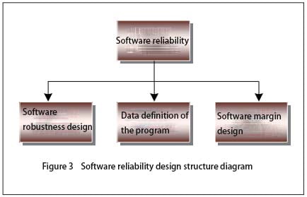
In the design of the hardware interface software of the sensor, the failure detection of the external input or output device must be considered first, and when the failure is detected, the software can restore the interface to a certain safe state, and the hardware failure mode involved is also required to be considered. When the sensor transmits data, in order to ensure the authenticity and reliability of the data received by the receiver, the data sent by the sender is required to use a specific format and content, so that the sender and the receiver can use the agreed method for verification. In the process of software design, its reliability design structure is shown in Figure 3.

When the software program of the sensor is written, the first thing to consider is the robustness of the software. In software robustness design: First, the power module of the inclinometer sensor may have intermittent failure at the moment of power supply, so that the inclinometer sensor into a potential unsafe state, in order to avoid this state, it is required that the software safely shut down the sensor when the sensor power supply fails, in addition, the power supply of the inclination sensor may have abnormal fluctuations. Software is also required to handle it; Second, the software design must take into account a self-test when the sensor is powered on, verifying that the sensor system itself is safe and can operate normally, and when necessary, the sensor can carry out periodic self-testing; Third, the inclination sensor needs to work normally in electromagnetic radiation, static interference and other environments, which requires the sensor hardware circuit design to be processed according to the technical requirements, so that the sensor can control the external interference within the specified range, when there is external interference, the software is reset again, so that the sensor can still operate normally. Secondly, it is necessary to carry on the margin design when writing the sensor operation program. While ensuring the storage capacity and data channel transmission capacity of each module of the software, the software margin of the inclination sensor should be planned to ensure that the software margin meets the requirements. According to the specific state of each subsystem during software running, the arrangement of various cycles and working time series of software is determined to ensure that sufficient margin is reserved between software working time series.
Finally, consider the data definition when the sensor program is written. When defining the data in the software operation process, it is necessary to ensure that the defined data must be within a reasonable range, so that the sensor can ensure the size and error of the value within the specified range during the data operation process to ensure the accuracy of the data operation. In addition, reasonableness checks are also carried out at the entrance, exit, and other key locations of the software.
2.3 Structural reliability design
In addition to the protection of the external environmental stress, the electromagnetic compatibility of the inclinometer sensor is mainly optimized in the structure of the sensor. Under modern conditions, electromagnetic interference is everywhere, in this environment to make the sensor normal operation, it is required to optimize the sensor in hardware circuit, overall structure, manufacturing process, etc., in order to reduce the sensitivity of the sensor for interference, so that the external entry and internal leakage of electromagnetic interference can be controlled in a acceptable range.
2.4 Process reliability design
Process reliability design is mainly divided into printed board reliability design, electrical interconnection design and “three defenses” design. The reliability design of the printed circuit board requires the layout of the entire circuit board to be reasonable, and a single functional module or functional circuit is placed on a panel as far as possible, which is more convenient for later troubleshooting and maintenance. The circuit board should be rationally arranged on the circuit board, the circuit at all levels should be arranged and combined according to the distribution of the schematic diagram, the input and output of the sensor should be arranged separately, the analog circuit module and the digital circuit module should be isolated, the layout and wiring should be reasonable as far as possible, and the generation of parasitic coupling electromagnetic interference should be suppressed. When placing electronic components on the circuit printed board, it is required to be as suitable as possible for visual inspection of the entire circuit printed board, to facilitate the inspection of the nominal value of electronic components and fault location. When placing large and heavy components on the circuit printed board, it is necessary to reinforce them to prevent damage to components caused by vibration and impact of the sensor and make the sensor unable to operate normally. The design of electrical interconnection requires the sensor process specification to specify the installation and welding temperature and time of the components, the welding specifications of the inserted components and the operating conditions of the welding operators. The “three defenses” design requires the developer to fully understand the use environment of the sensor, master the characteristics of the sensor use environment and the law of change, analyze the stress conditions of the sensor failure in its use environment, and finally choose the suitable defense for the sensor
Enclosures, materials and sensor manufacturing processes.
3 Summary
By analyzing the reliability of inclinometer sensors in the process of development, production and use, we integrate the reliability design of wireless ER-TS-12200-Modbus and single-axis ER-TS-3160VO, ER-TS-4150VO and other tilt sensors into the development and production of sensors. Through the reliability information collected by customers during the use of such products, the reliability assessment of the sensor is carried out, and the reliability improvement of the tilt sensor is finally completed.
High Performance Navigation MEMS IMU
ER-MIMU-02 (0.05 deg/hr)
1. 3 axis gyroscope & 3-axis accelerometer;2. High performance and small size;
3. Gyro bias instability: 0.05 deg/hr.
ER-MIMU-02 uses MEMS accelerometer and gyroscope with high quality and reliability, RS422 and external communication, baud rate can be flexibly set between 9600~921600, through the communication protocol to set the user’s required communication baud rate. With X, Y, Z three-axis precision gyro, X, Y, Z three-axis accelerometer with high resolution, can be output by RS422 X, Y, Z three axis of gyroscope and accelerometer’s original hexadecimal complement data (including gyro hexadecimal complement the numerical temperature, angle, the accelerometer hexadecimal temperature, the acceleration hexadecimal complement number); It can also output float dimensionless values of the gyroscope and accelerometer processed by the underlying calculation.
Application areas
Antenna and Line of Sight Stabilization Systems
Integrated Navigation Systems & Inertial Guidance System
Flight Control & Guidance System
Attitude Heading Reference Systems (AHRS)
Stabilization of Antennas, Cameras & Platforms
Aerial and Marine Geo-mapping / Surveying
Why Is Gyro Steering Replacing Traditional Magnetic Steering in High-Stakes Projects?
Precise directional measurement is the core technology for ensuring the wellbore follows the planned trajectory, effectively avoiding adja...

-
For more information, please indicate in the “Ask for a Quote” box at the bottom of the page that you learned about this North Finder fr...
-
Horizontal directional drilling technology completes the task of laying underground pipelines without destroying the surface environment....
-
With the advantages of all-solid state, high performance and flexible design, fiber optic gyroscope has become the mainstream inertial...


.jpg)
