Saturday, April 6, 2024

Take you to briefly understand IMU

 https://www.ericcointernational.com/application/take-you-to-briefly-understand-imu.html

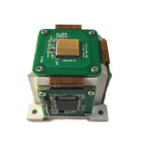
IMU is the abbreviation of Inertial Measurement Unit. It is a sensor composed of an accelerometer, a gyroscope and a magnetometer, which is used to measure the motion status of an object such as angle, speed and acceleration. The accelerometer is used to measure the object's acceleration and gravity, the gyroscope is used to measure the object's angular velocity and gravity, the gyroscope is used to measure the object's angular velocity, and the magnetometer is used to compensate for the interference of the geomagnetic field on the gyroscope.


As the core component of the inertial navigation system, IMU can help the system achieve autonomous navigation and positioning without being restricted by GPS, and has wide application value. It can play a role in a variety of fields such as drones, robots, missiles, aircraft, ships, camera stabilizers, etc. The magnetometer is used to compensate for the interference of the geomagnetic field on the gyroscope. The technology and parameters of IMU will be introduced below.

Features of IMU technology:

  1. High accuracy: IMU can achieve high-precision measurement and prediction of motion status, and can achieve high measurement accuracy.
  2. Compact and lightweight: The IMU is very small and can be equipped on various devices, such as drones, robots, etc.
  3. Degree of freedom of motion: IMU can measure acceleration, angular velocity and magnetic field in three axes, and can achieve various combinations of six axes, nine axes, etc. to meet the needs of different applications.
  4. Low energy consumption: The IMU has very low power consumption and can meet the needs of long-term continuous use.

Parameters of IMU technology:

  1. Accelerometer: It can measure the acceleration of an object (including static and dynamic acceleration) and the acceleration of gravity, and can also measure the inclination angle of the object.
  2. Gyroscope:It can measure the angular velocity of an object, also known as the rotational speed or rotation rate of the object.
  3. Magnetometer: It can measure the geomagnetic field and can be used to help solve the direction and angle of objects.
  4. Data frequency:IMU can output data at different frequencies, such as 100Hz, 200Hz or 1000Hz. The higher the data frequency, the stronger the real-time nature of the data.

Application areas

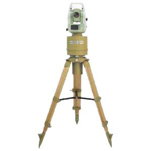
IMU technology is widely used, from satellites to subways, from aircraft to spacecraft, from drones to robots, everywhere. It can help devices achieve autonomous navigation and positioning, and can also be used in areas such as attitude sensing, tilt compensation, and vibration suppression. IMU technology is widely used in military, civilian, scientific and medical fields.


The emergence of IMU technology makes up for the shortcomings of GPS positioning. The two complement each other and enable autonomous vehicles to obtain the most accurate positioning information. It is worth noting that the IMU provides relative positioning information. Its function is to measure the path of an object relative to a starting point, so it cannot provide specific location information about your location. So often used with GPS. When in some places where the GPS signal is weak, the IMU can play its role, allowing the car to continuously obtain absolute position information to avoid getting "lost." In fact, although the IMU technology seems strange, in fact, IMU is used in the mobile phones, cars, airplanes, and even missiles and spacecraft that we use daily. The difference is cost and accuracy.


According to different usage scenarios, there are different requirements for the accuracy of IMU. High precision also means high cost.


Low-precision IMU: Used in general consumer electronics, this low-precision IMU is very cheap. Widely used in mobile phones and sports watches, often used to record steps. ​


Medium-precision IMU: used in driverless cars, with prices ranging from a few hundred to tens of thousands of dollars, depending on the positioning accuracy requirements of the driverless car.


High-precision IMU: for missiles or space shuttles. Take missiles for example. From the time the missile is launched to hitting the target, the aerospace IMU can achieve very high-precision calculations, and the error can even be within one meter.

Conclusion

IMU technology has been developing rapidly. With technological innovation in various fields, the application scenarios of IMU technology will become more and more extensive.ERICCO INERTIAL SYSTEM has conducted more in-depth research on IMUs. For example, ER-MIMU01 can independently seek north and uses high-quality and reliable MEMS accelerometers and gyroscopes. It is equipped with X, Y, Z three-axis precision gyroscopes, X, Y, Z three-axis accelerometer, with high resolution, can output the original hexadecimal complement data of X, Y, Z three-axis gyroscope and accelerometer through RS422 (including gyroscope hexadecimal complement) numerical temperature, angle , accelerometer hexadecimal temperature, acceleration hexadecimal complement); it can also output floating point dimensionless values of gyroscopes and accelerometers processed by underlying calculations. If you want to better study and master IMU technology, it is necessary to study subjects such as physics, mathematics, and computer science. I hope this article will help you understand IMU. Ericco also has a variety of high-precision IMUs. Welcome to learn more!


Tuesday, April 2, 2024

Miniaturized FOG Inertial Measurement Unit

 Fiber optic gyroscope is a new type of angular velocity sensor based on Sagnac effect. Compared with mechanical gyroscope, fiber optic gyroscope has the advantages of all-solid structure, strong impact resistance and short start-up time. Compared with laser gyro, it uses passive fiber ring as the sensitive medium and has no blocking effect.

Since Vali and Shorthill demonstrated the feasibility of measuring angular velocity in the laboratory with the Sagnac interferometer in 1976, more than four decades of technological progress have been made. At home and abroad, including Honeywell, NorthropGrumman, Liton, Beijing University of Aeronautics and Astronautics, the 33rd Aerospace Science and Industry Group, the 502nd Aerospace Science and Technology Group, Ericco and other units have developed mature fiber optic gyro products, measuring accuracy covers high, medium and low precision applications. And has begun mass production, in many fields have replaced the traditional mechanical gyroscope.


Inertial measurement unit (IMU) is the core component of inertial navigation system (INS). With the development of fiber optic gyroscope technology, the FOG Inertial Measurement Unit as the angular velocity sensitive component has been maturely applied in aviation, aerospace, weapons and other fields, greatly improving the performance of inertial navigation system. However, in some special fields such as deep space exploration and manned spaceflight, the inertial navigation system has higher requirements for the volume, power consumption and reliability of FOG Inertial Measurement Unit due to the constraints of space environment and spacecraft loads. In order to meet the application requirements of miniaturized and low-power FOG Inertial Measurement Unit for inertial navigation systems in aerospace market, a design and implementation method of miniaturized FOG Inertial Measurement Unit is proposed. The results show that the weight of IMU components is 2.342 Kg, and the power consumption is 10.6 W at normal temperature, which can meet the requirements of IMU in inertial navigation system.


1. IMU design scheme
The framework of the miniaturized FOG Inertial Measurement Unit is proposed, which consists of two parts: IMU module and IMU circuit. The IMU assembly consists of four fiber optic gyroscopes and four quartz flexible accelerometers. The fiber optic gyroscopes/accelerometers receive the secondary power supply provided by the IMU line and output telemetry and pulse signals. The IMU component adopts the 4S structure scheme, and any three-axis fiber optic gyro/accelerometer can complete the angular velocity/acceleration measurement function, with 1 degree redundancy. The IMU circuit consists of a primary interface circuit, a backup interface circuit, and a power management circuit. The primary and backup interface circuits have the same functions and are used in cold backup. The interface circuit receives the primary power supply provided by the inertial navigation system, provides the secondary power supply to the fiber optic gyro/accelerometer, collects the output signal of the fiber optic gyro/accelerometer, and communicates with the inertial navigation system. The power management circuit works with the main and backup interface circuits to complete the independent power-on and power-off control of four fiber optic gyros and four accelerometers.
Interface circuit, power management circuit, accelerometer, fiber optic gyro are the important components of IMU, and their volume and power consumption directly affect the product status of IMU. After more than 40 years of technological progress, the technology of miniaturized fiber optic gyroscope has been relatively mature.


2. Design results
Through the interface circuit based on SIP device LSMEU01 and the miniaturized power management circuit based on magnetic hold relay, the volume of IMU circuit is reduced by about 1/2 and the weight is reduced to 0.778 Kg. The single-meter power consumption of the accelerometer is reduced to 0.9W by using the temperature compensation method based on the combined parameters. By using this measure, we can effectively reduce the volume and power consumption of IMU. The results show that the weight of IMU components is 2.342 Kg and the power consumption is 10.6W at normal temperature, which can meet the needs of the use of minisized IMU in inertial navigation system.


3. Summary
Ericco's ER-FIMU-50 is the smallest FOG Inertial Measurement Unit, which is widely used in AHRS, guidance and control systems, onboard attitude measurement inertial/satellite integrated navigation system, drilling system mobile mapping system, and satellite communication in motion. If you would like to obtain more technical data, please feel free to contact us.

Thursday, March 28, 2024

Large Outdoor Advertising Monitoring Based on Tilt Sensor

 When it comes to the use of tilt sensors to monitor angles, people's first reaction may feel very strange, in fact, we often use the mobile phone has a similar function, it is easy to search the relevant app in the mobile app store, and it is also very convenient to use, although there may be no one in the work really use the mobile phone as a measurement tool. But we can fully see that the measurement of the tilt Angle has been very easy.

At present, the inclination sensors used in many fields are basically based on MEMS (Micro-electro Mechanical System for short, Chinese name micro-electro-mechanical system) tilt sensors, around 1960, the United States took the lead in studying MEMS technology, Then France, Germany, Switzerland, Japan and other countries also began to pay attention to MEMS research work, China's MEMS research began in 1989, to 1999, China's domestic MEMS research and development units have reached more than 50, the level of scientific research can also be placed in the international top ten. As of 2010, there are about 600 units engaged in the research and production of MEMS in the world.
MEMS is an independent intelligent system, which integrates micro sensor, signal processing, actuator, interface circuit, control circuit, communication and power supply in one. It has the advantages of small size, low power consumption, light weight, strong durability, high stability, low price and easy mass production. It can be seen that MEMS refers to a system that is integrated by multiple devices. The current research on MEMS technology mainly includes: micro-mechanical pressure sensor, micro-gas sensor, micro-acceleration sensor, micro-flow sensor, micro-mechanical gyroscope, micro-mechanical temperature sensor and other micro-mechanical sensors.
Mems-based sensors have many uses, measuring tilt angle is just one of them, using acceleration sensors, such as gas flow measurement, temperature measurement, pressure measurement, and so on.
The application of MEMS technology to monitor the tilt angle of large outdoor advertisements is not a blind decision.

1. Monitoring methods for large-scale outdoor advertising
At present, there are four main monitoring methods for large-scale outdoor advertising:

(1) Camera monitoring
Due to the large outdoor advertising area is large, very eye-catching, mostly erected in bustling areas, highways and overpasses near, these geographical locations are also key jurisdiction areas of the city, therefore, these areas are basically covered by urban surveillance cameras, administrators can view large advertising and its surrounding situation through real-time monitoring. Although this monitoring method seems to have the characteristics of real-time, but it is difficult to achieve in practical applications, the monitor can not always stare at the surveillance video, and when the visibility is low, the effect of the surveillance video will be reduced a lot, affecting the observation of the monitor, therefore, the use of this method to monitor large-scale advertising is not ideal.

(2) Regular manual inspection
Surveyors field measurement is the most traditional monitoring method, the longest application time, the monitoring process is relatively mature,
This method is mainly used by inspectors to measure large advertisements using steel tape, optical theodolite, portable ultrasonic flaw detector, weld gauge, rebound meter and other equipment. Due to the support of high-precision data, this method has high credibility, but in order to achieve rapid and comprehensive monitoring of all large advertisements, not only need multiple sets of monitoring equipment. It also needs to use more manpower and material resources, which is very inconvenient, and this method is mainly preventive, which cannot achieve real-time understanding of large-scale advertising conditions, so this method is not ideal.

(3) Monitoring based on radio frequency technology
The technology is a non-contact automatic identification technology that emerged around 1990, which carries out non-contact two-way data transmission between the base station and the radio frequency card to achieve the purpose of identifying the target and data transmission. This method mainly uses 2.4GHz active radio frequency electronic tag to record the attribute information and location information of large advertisements. The electronic tag can sense the displacement, and a receiving base station is required to receive, process and transmit the data sent by the electronic tag. The technology is widely used in many fields such as small advertising management, highway ETC express lanes, logistics, retail and so on.
Although this method can obtain the position data of large advertisements in real time, it is not its strong point in monitoring the tilt Angle. This method can make up for the shortcomings of the above two methods, but the final result can not measure the tilt of large advertisements

(4) Sensor-based inclination monitoring
Tilt sensor is often used to measure the change in inclination relative to the horizontal plane, it is based on Newton's second law as a theory, according to the basic principles of physics, in a system, the speed can not be measured, but can measure its acceleration, under the condition of the initial speed is known, you can use the integral method to calculate the line speed, and then calculate the linear displacement. So it's an acceleration sensor that uses the principle of inertia. The tilt sensor is fixed on the back of a large advertisement, and the single chip microcomputer is used as the central controller to integrate the monitored angle data, monitoring time, monitoring site number and other information, and then through the General Packet Radio Service (GPRS), The wireless communication module will send out the packaged data, and the data will be analyzed and processed by the monitoring personnel, and this equipment is powered by solar energy + battery, making the equipment more independent and easier to manage. This method can understand the angle information of large advertisements in real time. In the case of investing very little manpower and material resources, you can fully understand the situation of each large advertisement, and the data credibility is high, so this way is more ideal.

2 Summary
In summary, after a more detailed analysis of various monitoring methods, it is not difficult to see that the method based on tilt sensors is the best to use this method to monitor the tilt of large-scale outdoor advertising. Ericco has various precision and types of tilt sensors, like ER-TS-3160VOER-TS-12200-Modbus, widely used in Bridges, DAMS, building monitoring and other fields, if you want to buy or want more technical data of tilt sensor, you can contact us at any time.

Tuesday, March 26, 2024

FOG Inertial Measurement Unit Data Acquisition System

 According to the application background of a project, a strapdown inertial measurement unit (FOG Inertial Measurement Unit) is designed and implemented with open-loop fiber optic gyro and silicon micro-accelerometer as inertial sensing components and high-speed DSP as signal processor. The system implements the basic function of sending out angular velocity information and specific force information every 10 ms. Considering the operating characteristics of the system, corresponding measures are taken in the design of software and hardware of the system to ensure the accuracy of the system, improve the real-time performance of the system, and expand the system function. Finally, the system is tested, and the results show that the system has reached the expected design goal.

The inertial navigation system can measure the carrier's heading, attitude and position in real time. Compared with the platform inertial navigation system, the strapdown inertial navigation system replaces the electromechanical physical platform with the "mathematical platform" stored in the computer. The measurement data of the gyroscope and accelerometer are collected by the computer, and the information such as the position, attitude and heading of the carrier is obtained through solving, which is used for the control and navigation of the carrier.

Compared with the traditional flexible gyro, the optical fiber gyro has the advantages of anti-impact and anti-acceleration, short start-up time, high sensitivity and resolution, wide dynamic range, low price, etc., which is suitable for the use in harsh environment, because it is more suitable for the construction of strapdown inertial measurement unit.
Fiber optic gyro strapdown inertial navigation system has become one of the most important development directions in many fields such as aerospace, aviation, maritime and land navigation. At present, fiber optic gyroscopes have obvious advantages in the application range of medium and low precision (0.01 ~ 30 ° / h). Mems-based silicon micro-accelerometers have also been able to achieve 10-3 g or even higher accuracy, and the volume is very small, easy to integrate the system. The strapdown inertial measurement unit using fiber optic gyroscope(FOG Inertial Measurement Unit) and silicon microaccelerometer has the advantages of low cost and small size, and has broad application prospects in both military and civil fields.

1 Overall design of the system
According to the overall requirements of the system, the inertial device selection and system structure design are carried out. Through the error transfer equation of strapdown inertial navigation system, the error analysis and computer simulation results show that the open-loop fiber optic gyro and silicon micro-accelerometer with low precision can meet the requirements of the system index.
The system consists of mechanical structure, three fiber optic gyroscopes, accelerometer components and processing circuit. In the structural design, the sensitive axes of the tourmala components are mutually orthogonal; The accelerometer component composed of 3 circuit boards ensures that the 3 sensitive axes are vertically intersected with the space point during PCB design; The non-orthogonal error of the system can be compensated by software through calibration.

2 Data acquisition module
The data acquisition module mainly completes the functions of sampling, analog filtering, amplifying and modulo conversion of the output signals of 3 doloris and 3 accelerometers. In order to improve the acquisition accuracy of the inertial measurement unit, the pre-processing circuit of the inertial device is designed. The gyro and accelerometer outputs are converted into single-ended and unipolar voltages by two-stage op amp and analog filter, and then A /D conversion is performed. The module collects 8 analog signals, in addition to 3 gyro signals and 3 accelerometer signals, accelerometer chip temperature and ambient temperature are also collected for temperature compensation.

FOG Inertial Measurement Unit Data Acquisition System A D convert

3 Summary
In this paper, the open loop optical fiber toralon and silicon micro-accelerometer are used as inertial devices to design and implement the inertial measurement unit which is applied to the medium and low precision and short time operating system. It can be seen that the data acquisition system has reached the performance index specified in the medium-precision strapdown inertial navigation system. At present, the system has been used in some prototypes of strapdown inertial navigation system and runs well. Ericco has several cost-effective, low-cost FOG inertial measurement units ER-FIMU-50ER-FIMU-60ER-FIMU-70, if you want to get more technical data of FOG inertial measurement units, please feel free to contact us. 

The Working Principle and Method of North Finding of Gyro Theodolite

https://www.ericcointernational.com/application/the-working-principle-and-method-of-north-finding-of-gyro-theodolite.html

Definition

Gyro theodolite is a directional positioning instrument, which is composed of two parts: gyroscope and theodolite. This instrument is a theodolite with a gyroscopic device used to determine the true north azimuth of the line. It uses the precession and fixed axis of the gyroscope itself, sensitive to earth rotation, and can quickly and accurately give the true north position of the measured point anywhere within 75° north and south latitude, so as to determine the true north azimuth of any target.

Gyro theodolite is used to measure the true azimuth simply and quickly, and is not limited by time. It is often used to measure roads, railways, tunnels and mines. The above content is for reference only, if you need detailed information and data of gyrotheodolite, it is recommended to consult relevant professional books or consult experts in the field of surveying and mapping.

1.North seeking working principle of Gyro Theodolite

1.1 Earth’s rotation and gyroscopic precession

The earth is a constantly rotating object. It rotates around the earth's axis with ωE; therefore, all objects on the earth also rotate at the same time. When you look down at the Earth from above the North Pole, you can find that the Earth's rotation is counterclockwise, and the angular velocity vector ωE points toward the North Pole along the Earth's rotation axis. Assume that the ground point P is at a position with a latitude of ϕ, and the angle between the direction of the earth's rotation angular velocity vector and the horizontal plane at this point is ϕ. At the ground point P, the ωE vector can generally be decomposed into a horizontal component vector ω1 (along the ground The tangent direction of the meridian where the point is located) and the vertical component vector ω2 (along the vertical direction of the meridian where the ground point is located).

Figure 1(b) shows the position of the auxiliary celestial sphere above the ground. Assuming that the center of the earth is O, the earth can be regarded as a point for various celestial bodies other than the earth. If the gyroscope and the observer are both at point O, and the x-axis of the instrument is in the horizontal direction, east of the true meridian, the angle between the two is α. which level

The formula for calculating the components is


Figure 1 Schematic diagram about angular velocity of earth rotation

The rotational component ω2 is the speed at which the gyro rotates around the Z-axis at its ground position. The most direct experience is that the northern end of the meridian moves toward the west. It can be called the vertical component of the rotation of the Earth's sphere. What an observer on the earth experiences is the relative relationship between the heights of other planetary bodies and the sun in inertial space. Therefore, the calculation formula for the vertical component of angular velocity is as follows

In order to specifically express the motion of the gyroscope due to the rotation of the earth, the horizontal rotation component ω1 is further decomposed into factors ω4 (along the x-axis direction) and ω3 (along the y-axis direction), where

Considering that when the earth rotates as a whole, the gravitational moment on the instrument will push the gyro's polar axis to move along the x-axis, generating a force that returns to the meridian plane where the gyro is located; when the polar axis moves to the ground plane due to the force of the hanging weight (as shown in Figure 1(a) )), does not produce a hanging weight moment, so it has no effect on the change in the orientation of the x-axis [24]. However, since the earth is in a state of constant rotation, the gyroscope main axis and the ground plane are not parallel to each other at the next moment. Intuitively speaking, the positive direction of the x-axis of the gyroscope main axis is raised again relative to the ground, and the angle between it and the ground is different. θ (see Figure 1(b)). Therefore, the moment effect caused by the hanging weight will push the main axis of the instrument to precess in the direction of the meridian plane. Assume that the gravity of the sensitive part of the rotor is P and the center of the rotor is located at position O1. Let the distance between the center of gravity and point O be l. Therefore, considering the rotation of the ground plane around the y-axis, the final rotational moment is:


The precession angular velocity of the x-axis of the instrument spindle is


Therefore, the main axis of the instrument always precesses toward the meridian under the action of the effective factor component ω3 of the earth.

Figure2 Relationship between axis of gyroscope and heavy torque

2.Orientation method of Gyro Theodolite 

The orientation process of the Gyro Theodolite can be divided into coarse north-seeking orientation and fine north-seeking orientation. In coarse north seeking orientation, gyro orientation generally uses the two reversal point method, the three-point timing method, the quarter period method, etc. The most commonly used methods for precise north orientation include the four-point method, the Midheaven method, the integral method, the Shula average method, the Thomas average method, etc.

2.1 Reversal point method

The reversal point method is a gyro orientation measurement method in which the aiming part of the gyro is at the tracking target. It is generally used on rack-mounted suspended Gyro Theodolites. In the process orientation using the reversal point method, we are required to always keep the sighting part in a tracking state, observe and record multiple sets of swing endpoint values, and use this method to calculate the gyro north-seeking direction value. The reversal point method gyro orientation As shown in Figure 3.

Figure3  Method of Observation with Reversal Point

2.2 Zhongtian method

When using the mid-heaven method for gyro directional observation, since the sighting part of the gyro theodolite is in a fixed state at this time, this is a twisted observation. This method requires that when we initially place the gyro, the north direction of the gyro must be approximately within 15′ of true north. When using the mid-heaven method for gyro orientation, generally first fix the sighting part on the gyro theodolite at an approximate north direction N', and record the value of the approximate north direction. Zhongtian method gyro orientation requires that during the entire orientation process, the upper sighting part of the instrument must have a fixed direction and not change.

When using the Midheaven method for observation, the observation time is required to be at least one cycle, and at the same time, the Midheaven time of the Midheaven method can be read through cooperation; usually five Midheaven values can be used for observation and recording, and the untracked swing period also needs to be obtained.

2.3 Integration method

The principle of integral orientation is the same as that of mid-heaven orientation. It also needs to be initially placed in the basic north direction to proceed to the next step. However, the different characteristics of the two methods of orientation are: the Zhongtian method collects multiple point values in the gyro swing for calculation, and has discrete characteristics. The principle of the integration method is to read and capture a large amount of complete data of the gyro's precession swing when the gyroscope precesses, and comprehensively consider the information of each sampling point, so the final north-finding effect is also the best.

2.4 Thomas average method

The Thomas average method is a north-finding algorithm used by gyroscopes when accurately seeking north. The gyro average method collects the values of more than 7 reversal points of the gyro swing stability value, and finally calculates the value of the gyro's north direction through formula calculation. Since the data collected by this method is relatively comprehensive and complete, this method is widely used in the gyro. The total station's accuracy in finding north also works well.

2.5 Damping method

The damping method north-seeking orientation is a north-seeking method that uses the reverse torsional moment when the gyroscope swings, ultimately causing the sensitive part of the gyro to swing rapidly and converge to the true north direction; during this process, the sighting part needs to track the sensitive part at all times. The swing finally converges with the north direction together with the sensitive part. There are many types of damping torsion torque, generally such as electromagnetic torque, suspension torsion torque, etc. The general principle of damping torque is: when the gyro swings to the reversal point, the personnel performs precise tracking and observation of the reversal point through the horizontal micro-motion spiral of the total station, lasting 5-7 times, until the swing amplitude gradually decreases, and finally stabilizes in the north direction. .

Summarize

This chapter mainly introduces the definition of the Gyro Theodolite and the working principle of north seeking, explains in detail the north seeking orientation process of the Gyro Theodolite, and analyzes the orientation principles and accuracy of several orientation methods of the Gyro Theodolite. If you want to learn about or buy a Gyro Theodolite, ERICCO's Gyro Theodolite, such as ER-GT-02, can achieve ultra-high-precision north seeking. Its measurement principle is the integration method, which has strong anti-interference ability and stability. High characteristics. The gyro-theodolite adopts an integrated body design (built-in battery), with compact structure and stable performance. It has functions such as low-level locking, automatic zero-position observation, automatic north seeking, automatic limit, and wide temperature compensation. It is gradually iterating the limiter to provide the north seeking accuracy of the reference plane azimuth angle and reduce the north seeking time.

Welcome to consult and purchase.

Monday, March 25, 2024

Fiber Optic Gyro Track Accuracy Detection

 1. Principle of fiber optic gyroscope instrument inspection vehicle

1.1 Working principle of fiber optic gyroscope
It is assumed that two beams of light with the same characteristics are formed from the same light source in a closed optical path and propagate in opposite directions, and the angular speed of the optical fiber coil rotation in space is calculated by the optical path difference generated by the two beams at the convergence point, that is, the Sagnac effect.
The following diagram shows the Sagnac effect. X is the incident point of the beam, Y is the exit point of the beam, and Ω is the angular rate.

sagnac

1.2 Principle of chord measurement
The detection technology of track irregularity based on fiber optic gyroscope (FOG) is an advanced track detection method in the current string measurement method. Using the gyroscope to measure the Angle, the transfer equation between the track direction is changed by the Angle of the track detector, and the track direction irregularity data is obtained.
2. Analysis of measurement results
2.1 Test scheme
The school has a good surrounding environment, stable geological conditions and good visibility conditions, which provides a favorable external environment for the implementation of the program. The converted length of the track is about 1040m. Among them, about 110m of ballastless track can be used for the detection of the track inspection system.
Fiber optic gyroscope is the main sensor for measuring track irregularity with track inspection car, and its working characteristics are related to the accuracy of track inspection equipment. The test content of track smoothness mainly includes gauge, high height, high height, level, track direction and so on.
We mainly introduce the gauge, level and track direction.
The distance between the 16 mm position under the inner side rail surface of the two rail heads is called the gauge. The difference between the top height of the two rails is called the level. Through repeated measurement of the track level, gauge and track direction of the detection field, the relative internal and external coincidence measurement accuracy of the track detector based on fiber optic gyroscope is verified. The stability of the measuring system, that is, the difference of the measurement results when the track detector repeatedly measures the geometric state parameters of the same section of track. External coincidence accuracy indicates the accuracy of the track inspection equipment, that is, the difference between the measured results and the reference value of the track geometric state parameters should be small enough. The measurement accuracy of internal coincidence is relative difference, and the measurement accuracy of external coincidence is absolute difference.
We use the level 0 digital display track ruler to measure the gauge and level at each mark of the track in the detection field for three times, and the average value is taken as the reference value of the gauge and level, and the average value of the track direction of the 3 times manual pulling string is taken as the reference value of the track direction. After the measurement is completed, the measured data are numbered according to the mark number, and then the measurement difference of gauge, water level, rail forward and forward push at each mark of the detection field track, the repeated measurement difference and the difference between each measurement value and the reference value are calculated, and the measurement accuracy is calculated.
2.2 Test results
The track detector distributed by the public works workshop is divided into two categories according to its different measurement data, one is relative track information detection, and the other is absolute track information detection. The two detection methods are respectively suitable for detection without track control network and detection with track control network. Both types of devices are hand-pushed, with absolute detection speed of 200m/h and relative detection speed of 4km/h. The median error of the difference meets the requirement of the difference limit, indicating that the accuracy of the track detector meets the requirement.
The mean error of the difference between the gauge measurement value and its reference value is slightly higher than the mean error limit, but within 3%, which basically meets the requirements. This result may be caused by the condition of the track detection field or human factors caused by the 0 level digital gauge measured by the gauge reference value measurement accuracy exceeds the limit. Based on this, it is considered that the accuracy of the track detector meets the requirements.

3 Summary
We use fiber optic gyroscope to measure the Angle, and change the transfer equation between the track direction by the Angle of the track detector, so as to obtain the track direction irregularity data. Ericco has high performance, low cost fiber optic gyro, like ER-FOG-851ER-FOG-910, pure solid state fiber optic gyro, long life, if you want to get more technical data, please feel free to contact us. 

Choose a suitable IMU to make your drone flight more stable and safe

         As one of the core components of drones, IMU plays an irreplaceable role. Its high precision, fast response and freedom from extern...