Tuesday, April 16, 2024

What is an Inertial Measurement Unit?


An inertial Measurement Unit (IMU) is a device that typically consists of a gyroscope for measuring angular rate and an accelerometer for measuring linear speed. In this article, we'll delve into the inner workings of an inertial measurement unit to explore all the relevant specifications and information you need to choose the right IMU for your application.

1. What is IMU?

An Inertial Measurement Unit (IMU) is a device that can measure and report the specific gravity and angular rate of an object to which it is attached. Imus typically include:
Gyro: provides angular rate measurement
Accelerometer: Provides specific force/acceleration measurement
Magnetometer (optional) : Measures the magnetic field around the system
Adding magnetometers and filtering algorithms to determine directional information results in a device called the Attitude and Heading Reference System (AHRS).
Imus are available in a variety of performance levels. According to the specifications of accelerometers and gyroscopes, they are divided into one of four categories:
Consumer/Automotive grade
Industrial grade
Tactical level
Marine class
These performance categories are often defined in terms of the sensor's operational bias stability, which plays such an important role in determining inertial navigation performance. The following table summarizes the various levels of performance for these specifications.

ClassCostgyroscope operation bias stabilityGNSS reject navigation timeapplications
Consumer< $10----Smartphone
Industrial grade100$- 1000$<10°/h<1 minuteUAV
Tactical level$5,000- $50,000<1°/h<10 minutessmart ammunition
Navigation class< $100,000<0.1°/ha few hoursmilitary

Let's dive into the specific sensors used in IMUs, namely accelerometers and gyroscopes.

2. Accelerometers

Accelerometers are the primary sensors responsible for measuring changes in inertial acceleration or velocity over time, and there are many different types, including mechanical accelerometers, quartz accelerometers, and MEMS accelerometers. MEMS accelerometers are essentially mass blocks suspended by springs, as shown in Figure 2. This mass block is called the test mass, and the direction in which the mass block is allowed to move is called the sensitivity axis. When the accelerometer is subjected to linear acceleration along the sensitivity axis, the acceleration causes the mass block to move sideways, and the amount of deflection is proportional to the acceleration.

Simple accelerometer modeling

3. Gyroscope

A gyroscope is an inertial sensor that measures the angular rate of an object with respect to an inertial reference frame. There are many different types of gyroscopes on the market with varying levels of performance, including mechanical gyroscopes, fiber optic gyroscopes (FOG), ring laser gyroscopes (RLG), and quartz /MEMS gyroscopes. Quartz and MEMS gyroscopes are typically used in the consumer, industrial, and tactical markets, while fiber optic gyroscopes cover all four performance categories. Ring laser gyroscopes typically have in-operation bias stability and range from 1°/ hour to less than 0.001°/ hour, covering tactical and navigation levels. Mechanical gyroscopes are the highest performing gyroscopes on the market with bias stability of less than 0.0001°/ hour in operation.

4. Magnetometer

A magnetometer is a sensor that measures the strength and direction of a magnetic field. While there are many different types of magnetometers, most MEMS magnetometers rely on magnetoresistance to measure the surrounding magnetic field. Magnetoresistive magnetometers are composed of permalloy, and their resistance changes in response to changes in the magnetic field. Typically, MEMS magnetometers are used to measure a local magnetic field that is a combination of the Earth's magnetic field and any magnetic fields generated by nearby objects.

Standard dipole magnet

5. How does the Inertial Measurement Unit (IMU) work?

A single inertial sensor can only sense measurements along or around a single axis. To provide a three-dimensional solution, three separate inertial sensors must be mounted together to form an orthogonal cluster called a triplet. This set of inertial sensors installed in a triplet is often referred to as a triaxial inertial sensor because the sensor can provide a measurement along each of the three axes. Similarly, an inertial system consisting of a 3-axis accelerometer and a 3-axis gyroscope is called a 6-axis system because it provides two different measurements along each of the three axes for a total of six measurements.
The Inertial Measurement Unit (IMU) measures and reports the raw or filtered angular rate and specific force/acceleration experience of the object to which it is attached.
The data output of the IMU is typically body frame acceleration, angular rate, and (optionally) magnetic field measurements.
The user is then responsible for determining the pose by implementing an independent fusion algorithm, such as a Kalman filter.

6 Summary

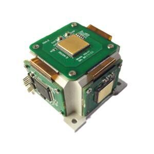
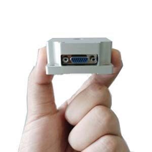
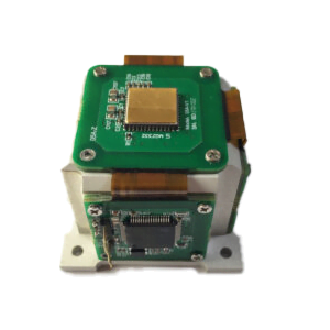
Ericco's FOG Inertial Measurement Unit ER-FIMU-50, gyro bias stability is 0.5°-1°/h, ER-FIMU-60, gyro bias stability is 0.1°-0.5°/h, these two belong to the tactical class of fiber optic IMU. ER-FIMU-70 gyro bias stability is 0.05°-0.1°/h, it belongs to the navigation level of fiber optic inertial measurement unit, mainly used in the inertial navigation of surface-to-air missiles, air-to-air missiles and navigation missiles, space stability system, mapping system, attitude reference system and other fields.

Research on inertial measurement unit output delay and time synchronization measurement method


As an important feedback link in the control system, the inertial measurement unit's delay characteristics of its gyroscope channel and accelerometer channel are an important technical indicator. In actual attitude control and navigation solution systems, the output delay of the inertial measurement unit is required to be as small as possible. The better the real-time performance, the easier it is for the control system to make timely and accurate attitude corrections. Then studying the measurement method of output delay is the key to accurately evaluate the dynamic performance of inertial measurement equipment. At present, conventional delay measurement only examines the output delay of the gyro channel, and does not involve the time asynchronous problem between the acceleration channel and the angular velocity channel. In order to make up for this shortcoming, this paper proposes an angular vibration test based on the sinusoidal swing motion of the angular vibration table. On the basis of the process, the synchronous acquisition of three accelerometer channel signals is added, the raw data of the gyroscope and accelerometer are converted into the frequency domain, and then the characteristic frequency points are extracted. Finally, the time delay is calculated from the phase angle of the characteristic frequency point and the time synchronization of the inertial device is achieved of calibration.


1.Delay analysis

The output delay of the inertial measurement unit is mainly affected by the superposition of its own structural transmission , the response of the gyroscope and meter-added inertial device, digital filtering, data transmission and other links.


Structural transmission: In order to ensure a good working environment for the inertial instrument, rubber shock absorbers are usually elastically installed between the inertial instrument and the measured carrier. The response delay for the angular velocity and linear velocity transmission in the low frequency band is negligible, but for high-frequency excitation There is a certain delay in response.


The response of the inertial device itself: Due to the influence of the structure and the sensitivity of the electronic devices, the gyroscope and the meter-added inertial device themselves have a certain delay when they are sensitive to external excitation.


Digital filtering: The digital signal processing of the gyroscope itself will cause delays to the entire system during the step height filtering and output signal filtering stages, reducing the ability of the inertial instrument to track external inputs, and there is some inherent delay. After the inertial measurement unit collects instrument data, it needs to undergo low-pass filtering to remove signal noise. If the filter order is high, the phase group delay generated will affect the system response time. Taking the 50th-order FIR low-pass filter as an example, from the amplitude-frequency phase-frequency curve of the digital filter in Figure 1, we can find that: 2kHz sampling data, the phase delay generated by the excitation below 200Hz in the phase-frequency curve is linear, then the group The delay is a fixed constant value of about 12.5ms.

2.Time synchronization analysis

Research on traditional strap down inertial navigation system algorithms is based on ideal measurements from gyroscopes and accelerometers. However, in an actual IMU, the signal output of each inertial device may be asynchronous in time. The output time of the gyroscope may be later than the output time of the accelerometer, or it may be faster than the output time of the accelerometer. This is because the physical limitations of the sensor inside the inertial measurement unit will affect the conversion of the bandwidth signal, ultimately resulting in the time of the output parameter. Delay. The frequency band width of fiber optic gyroscopes is generally several thousand Hz, which is much higher than the frequency bandwidth of accelerometers, and will eventually be processed to a unified output frequency. This processing process may also cause desynchronization of the actual output signal. In addition, the filter before the AD converter may also cause additional delays in the gyroscope and accelerometer signals, which are determined by factors such as the time it takes the sampled information to be transmitted to the computer. In addition, the inertial device also needs to be processed by some auxiliary hardware to make the inertial device output a more accurate signal. Therefore, it is necessary to compensate for the sum of all physical delays of the accelerometer and gyroscope and additional software and hardware delays, that is, to test the time delay parameters through SINS. The calibration results in the process are partially compensated to synchronize the accelerometer and gyroscope outputs.


3.Measurement method

In order to fully measure the time asynchronous parameters between the three accelerometers, the time asynchronous parameters between the three gyroscopes, and the asynchronous time error between the inertial device and the standard output, the analog signal output by the closed-loop angular vibration table is used as the standard output time reference. The product under test is fixed at a certain distance from the center of the off-angle vibration table table through the vibration tooling (as shown in Figure 2). The digital signal output by the inertial measurement unit and the analog signal output by the closed-loop angular vibration table are collected by the signal receiving system and stored in the computer.


The angular vibration test is performed at a given maximum rotation angular rate of 10º/s to ensure that the input value at each frequency point remains consistent.


In the test, if the angular vibration table has an angular rate setting input, the maximum angular rate is set to 10º/s. If the angular shaking table is an amplitude setting input, the swing amplitude for each frequency needs to be calculated. The following numerical relationships exist between the two input methods. In the angular vibration test, the instantaneous rotation angle of the turntable is:

Then the instantaneous angular velocity of the turntable is:

When the maximum angular rate of the turntable rotation is known, it can be obtained from the turntable formula:

The angular vibration frequency and amplitude requirements obtained by the above formula are as shown in Table 1

Figure 2 Installation diagram

The gyro is sensitive to the sinusoidal rocking motion of the shaking table; due to the offset of the installation position, the meter has a lever arm effect, which produces centripetal acceleration during the swing process. The meter data in three directions will also reflect the characteristic frequency of the shaking table. The Fourier transform is used to respectively extract the analog signal (reference voltage) output from the closed loop of the angular shaking table and the swing frequency component in the actual output of the inertial measurement unit. Finally, the time delay is calculated and the calibration of the time synchronization of the inertial device is achieved.

Table 1 Angular vibration test frequency and amplitude relationship

4 Angular vibration test

4.1 Test process

The angular vibration test uses a pure strapdown optical fiber inertial group to conduct the test according to the installation method in Figure 2. During the test process, when the data frame sent by the inertial measurement unit is sent to the receiving acquisition system, the analog signal of the AD sampling angular vibration table of the receiving acquisition system is simultaneously triggered ( Reference voltage), and then send the inertial measurement data and reference voltage data package to the host computer test software. After the test is completed, the spectrum of the saved test data is analyzed to calculate the response delay of the inertial measurement unit and the asynchronous time between the inertial devices.


4.2 Test results

During the test, the angular vibration table was set up to swing at a frequency of 2Hz. The data output frequency of the inertial measurement unit was 2000Hz. The data were normalized to facilitate waveform comparison with the reference voltage. Perform FFT processing on the saved data of the meter channel and gyro channel to extract the characteristic frequencies, and compare the phase differences at the characteristic frequencies.

Figure 3 Characteristic frequency

Figure 4 Data Curve

Summarize

The above article describes the output delay and time synchronization measurement method of the inertial measurement unit, and conducts an angular vibration test on it. The test results show that the waveforms between the three gyroscopes of the inertial measurement unit (and between the three plus meters) are basically consistent. The asynchronous time between similar devices is not greater than 0.1ms, which is much smaller than the data sampling time and does not require compensation. The MEMS IMU independently developed by ERICCO is divided into navigation grade and tactical grade. For example, navigation grade ER-MIMU-01 and tactical and ER-MIMU-03 have relatively high accuracy. If you want to know more, please contact us.

Monday, April 15, 2024

What can Fiber Optic Gyroscopes be Used for?


1.What is a fiber optic gyroscope?

A fiber optic gyroscope (FOG) is a device used to measure angular velocity and direction. It provides extremely accurate rotational speed information with low maintenance costs and long service life.
Fiber optic gyroscopes are becoming more affordable, and the technology has proven beneficial for an ever-expanding array of different high-performance inertial navigation systems (INS). As a result, FOG has become the default choice for strategic and tactical level applications that require long-term navigation in environments where GNSS (Global Navigation Satellite System) is not available.

2.How does a fiber optic gyroscope work?

Fiber optic gyroscopes use the properties of light in closed circuits to estimate changes in direction. Two beams of light are sent in opposite directions in the fiber coil.
As the vehicle rotates, the beam traveling against the rotation experiences a slightly shorter path delay than the other beams, a phenomenon known as the Sagnac effect. The phase shift difference between the two beams is then used to estimate the rotation rate.

3.What is the difference between a ring laser gyroscope and a fiber optic gyroscope?

Similar to the FOG, the ring Laser gyroscope (RLG) is an optical gyroscope that utilizes the Sagnac effect. The main difference between the two is the way they are constructed, because a ring laser gyroscope uses a laser passing through a system of mirrors to determine the rotation of the vehicle, rather than a simple fiber optic coil.
In addition to requiring extremely high manufacturing precision and special mirrors, the RLG is also filled with gas, and the laser needs to be "dithered," or mechanically vibrated, to prevent laser locking to eliminate small rotations.
While both types of gyroscopes work similarly and are very accurate, the older toroidal laser gyroscope technology is more sophisticated due to its construction, requires more maintenance, and is generally more expensive. In contrast, the fiber optic gyroscope is a solid-state device that does not use a jitter mechanism, which means it does not produce any acoustic vibrations, making it more durable and reliable than the RLG. In addition, the application of fiber optic gyroscopes can be extended by changing the length and diameter of the fiber optic coils.

4.What is the difference between a fiber optic gyroscope and a MEMS gyroscope?

A MEMS (Micro-electro-mechanical System) gyroscope is a smaller, lighter gyroscope made from tiny devices. MEMS gyroscopes have significantly reduced SWaP-C, which means they are preferred for applications requiring small payloads.
FOG has higher inertial performance and lower deviation, making it the preferred solution for high-precision applications such as GNSS rejection environments or antenna pointing.

5.What can fiber optic gyroscopes be used for?

Fiber optic gyroscope technology facilitates a growing number of applications where accurate heading and navigation are critical. This includes both manned and driverless vehicles.
Surface Ocean Vehicles: Ocean survey vessels use fiber optic gyroscopes to determine pitch, roll, and heading in real time and build accurate position data for unmanned underwater vehicles (UUV). They are particularly useful for side-scan sonar and similar applications.
Undersea vessels: Manned vehicles (such as submarines) and UUVs (unmanned underwater vehicles), including autonomous underwater vehicles (AUVs) and remotely operated vehicles (ROVs), rely on fiber-optic gyroscopes for precise navigation in extremely challenging and dangerous environments at minimal cost. Or an unreliable source of absolute location. Rovs and AUVs for hydrology in particular benefit from FOG's precision.
Aviation: Helicopters can be subject to electromagnetic interference and can benefit greatly from FOG-based INS. Unmanned aerial vehicles (UAVs) and commercial aircraft typically require FOG-level performance to reduce the risk of losing GNSS locations while in flight. The accuracy of roll, pitch and yaw data is critical to the safe operation of the aircraft.
Defense: Ground-based defense vehicles must not rely on GPS/GNSS because of the risk of local interference or spoofing of these signals, or simply the risk of terrain blocking or altering satellite positioning data. Fibre-based INS allows these vehicles to operate seamlessly, preventing adversaries from gaining an advantage from these tactics.
Space exploration: Fiber optic gyroscopes are ideal for space applications due to their long service life, virtually maintenance-free, extremely low power consumption, and accurate navigation data.
Robotics: Directional data from the fiber optic gyroscope is used to navigate the robot, ensuring safe operation when adjusting for any changes in speed, position or acceleration.
Ericco's ER-FOG-50ER-FOG-60 small size, light weight, the use of digital closed loop mode, no wear parts, long service life, a wide range of applications, is our good choice, if you are interested in our products, please feel free to contact us.

Who Makes Fiber Optic Gyroscopes?


1.The use of gyroscopic technology

For more than 100 years, gyroscopic technology has been used to aid navigation in a variety of applications. Mechanical gyroscopes were relied upon for about 60 years until the invention of the ring laser gyroscope in the 1960s. However, it wasn't until the 1970s that fiber optic gyroscopes were developed, implemented, and became popular in a wide range of applications from submarines to spacecraft.
The goal of any gyroscope is to measure the angular rotation rate on any single axis. This is critical for determining the pitch, roll, and yaw angles in a system that requires reliable navigation information to function properly. Imagine a plane taking off, a NASA rocket diving, or a missile finding its target. Gyroscopes for such applications measure the angular rotation rate of each vehicle. This critical information is sent downstream to control and stabilize the vehicle. Each gyroscope provides this information with varying degrees of reliability and accuracy, so how does a fiber optic gyroscope differ from other gyroscopes?

2.Optical fiber technology

As the name suggests, fiber optic gyroscopes use fiber optics to perform their work. Fiber optics are made of glass and are used in many applications to transmit light from one point to another. Fiber optic cables are commonly used in telecommunications such as telephones and the Internet, and are extremely fast and reliable.

FOG technology

In a fiber optic gyroscope, this method of light transmission is not used to transmit information elsewhere, but is tightly wound in an independent closed loop within the gyroscope. This allows the fiber optic gyroscope to take advantage of the "Sagnac effect."

3.Sagnac effect

This phenomenon, discovered by French physicist Georges Sagnac, is at the heart of how every fiber optic gyroscope works.
Inside the gyroscope, the laser is used to send two separate beams of light through an optical fiber. Each beam travels in the opposite direction, propagating the entire length of the fiber, up to 5 kilometers. Each beam then returns to the light detector, recording its travel time.
Take an international flight at cruising altitude. The aircraft is stable, flying straight, level, with no rotation changes.
When there is no rotation change in the aircraft, the beam returns to the detector at the same time. In this case, there is no delay or "phase shift" between each beam. The aircraft was detected as stable and did not undergo any rotation rate around any given axis.
However, when the plane turns, Sagnac will come into full play. When the aircraft turns to the right, the fiber optic gyroscope dedicated to the rolling shaft will experience an arrival delay between the two beams. As it rotates, the distance each beam must travel changes.
When the detector is slightly closer to the traveling beam, the light traveling against the direction of rotation will return first. In this example, the beam propagating to the left will return first. Similarly, a beam traveling to the right will take longer. The phase shift between each beam is detected as a rotational change. This critical information can then be sent downstream to an aircraft, spacecraft, submarine or missile to stabilize it. This happens at a rate of hundreds of times per second, providing very precise measurements.

4.Fiber optic gyroscope calibration

As with any gyroscope, error sources, deviations, and noise must be carefully considered and corrected. During manufacturing, fiber optic gyroscopes are calibrated to correct for several potential sources of error that can be introduced by the gyroscope itself or the environment. When calibrated, fiber optic gyroscopes provide a very high level of performance.
Why use fiber optic gyroscopes?
Fiber optic gyroscopes have become ubiquitous in many applications, with several attractive properties. They remain reliable in harsh environments with intense vibration, have no moving parts, strike a good balance between price and high performance, and can last a long run.

5.Summary

Ericco developed fiber optic gyroscope ER-FOG-851ER-FOG-910, low cost, good performance, can be widely used in optical pod/flight control level, INS/IMU, platform stabilization device, positioning system, north finder, high precision measurement/navigation system and servo system, if you are interested in learning more, Please feel free to contact us.

Friday, April 12, 2024

IMU Calibration Using 12-position Method


High Precision Navigation MEMS IMU

Introduce

The 12-point calibration is a method used for the calibration of the Inertial Measurement Unit (IMU). IMU is a device that can measure the acceleration and angular velocity of an object and is widely used in aerospace, navigation, robotics and other fields. In practical applications, the accuracy of IMU is crucial to the accuracy and reliability of measurement results. Therefore, it is essential to correct the IMU error through calibration.


The 12-position method is a calibration method based on position changes. Its principle is to use mathematical models to calculate the error parameters of the IMU by recording the output data of the IMU at different positions and postures. Specific steps are as follows:


The first step is to determine the position: During the calibration process, a series of different positions and postures need to be selected. These positions should cover the entire measurement space as much as possible, and it is necessary to ensure that the output data of the IMU at these positions is reliable and accurate.


The second step is to collect data: At each position and attitude, fix the IMU on the object and collect the output data of the IMU. These data include accelerometer and gyroscope measurements. In order to improve the measurement accuracy, it is usually necessary to repeat the measurement multiple times and average it.


The third step is to establish a mathematical model: use the collected data to establish an IMU error model. This model can be solved through mathematical methods such as linear regression and least squares method. According to the parameters solved by the model, the output data of the IMU can be corrected.


The fourth step is to calculate the error parameters: According to the mathematical model, calculate the error parameters of the IMU. These parameters include zero bias, scale factor, non-orthogonality, etc. These parameters can be used to correct the output data of the IMU and improve the accuracy and precision of the measurement.


The fifth step is to verify the calibration results: The accuracy and reliability of the calibration results need to be verified. Some known accurate measurements can be used to compare the calibrated measurement results to ensure the validity of the calibration.


IMU calibration method using 12-position method


As a commonly used IMU calibration method, the 12-position method has the following advantages:

1.High accuracy: By performing calibration at different positions and postures, the error characteristics of the IMU can be more comprehensively considered and the accuracy and precision of the measurement can be improved.


2.Strong reliability: By repeating measurements multiple times and averaging, the impact of random errors can be reduced and the reliability of the calibration results can be improved.


3.Wide scope of application: The 12-position method is suitable for various types of IMUs, whether it is MEMS (Micro-Electro-Mechanical Systems) or fiber optic gyroscopes, etc.


4.Simple operation: The 12-position method does not require complex equipment and experimental conditions. It only needs to fix the IMU in different positions and postures for measurement.


However, the 12-position method also has some limitations:


1.It takes a long time: Since measurements need to be performed at multiple positions and postures, the calibration process is cumbersome and takes a long time.


2.High requirements for the test environment: Since the output of the IMU is affected by environmental factors, such as temperature, humidity, etc., the calibration process needs to be carried out in a well-controlled experimental environment.


Summarize

As a commonly used IMU calibration method, the 12-position method can effectively improve the accuracy and reliability of IMU measurement results. In practical applications, it is very important to select a suitable calibration method for IMU calibration based on specific needs and experimental conditions. Through calibration, the error of the IMU can be corrected and the accuracy of measurement can be improved to better meet the needs of practical applications. The MEMS IMU independently developed by Ericco has built-in gyroscopes and accelerometers. They have relatively high accuracy and can be used in many fields. For example, ER-MIMU-01 and ER-MIMU-05, welcome to learn more.


Wednesday, April 10, 2024

Why and Where are Tilt Sensors Used


1. Why do people monitor tilt angles?

The world is constantly changing, and the tendencies of different objects and machines can provide insight into worrying trends and potential future problems. There are many reasons why people need to monitor the Angle or degree of inclination.

Avoid accidents and injuries
One reason is that it can help prevent injuries and avoid accidents. When people work on the slope, they need to pay attention to the Angle of the slope to ensure that they do not slip. If the Angle is too steep, it can cause an avalanche, which is very dangerous.

Ensure the normal operation of the device
Another reason to monitor the tilt Angle, or tilt, is to make sure the equipment is working properly. For example, if a machine is not level, it may not work properly. This can be dangerous for the person using the device and the people around it.

2. Where can the tilt sensor be used?

Tilt sensors can be used in many applications, such as the Marine industry, construction industry, infrastructure monitoring, etc.

Marine industry
Tilt sensors can be used on ships to measure ship roll and pitch. This information can be used to improve the stability of the ship and avoid capsizing.
Construction industry
In many construction machines, such as excavators and bulldozers, tilt sensors can be used to measure the Angle of the machine blade or bucket. This information can be used to automatically adjust the position of the blade or bucket, or to provide feedback to the operator.
Infrastructure monitoring
Tilt sensors can be used to monitor the status of infrastructure such as Bridges and buildings and alert authorities to potential hazards, such as leaning towers. By continuously monitoring the tilt of the structure, the sensors can detect even the smallest changes that could indicate a problem. In the event of a potential accident, sensors can provide critical information that can be used to evacuate people and take other safety measures.
Tree bend monitoring
Some trees may fall after storms, typhoons or other natural disasters. Tilt sensors can be installed at a certain height on these trees to monitor their x, y, and z values in real time. This can provide insights into tree tilt and movement and help make timely, effective decisions to protect trees and people.
Gate monitoring
In car parking lots and parking garages, the normal operation of road gates is crucial to the normal toll collection. The tilt sensor can be installed in the guardrail housing, especially suitable for the guardrail Angle measurement and movement detection, to determine whether the guardrail is dropped, bent or broken, if there is a trigger alarm, so that maintenance personnel can take measures in time. Ensure regular charges.

3. Summary

Ericco's ER-TS-12200-Modbus precision up to 0.001°, the use of advanced Internet of Things technology Bluetooth and ZigBee(optional) wireless transmission technology, all internal circuits are optimized design, using industrial MCU, three-proof PCB board, imported cables, wide temperature metal shell and other measures, Improve the industrial level of products. Good long-term stability, zero drift small, can automatically enter low-power sleep mode, get rid of the dependence on the use of the environment, equipped with IP67-rated housing, so that it can withstand harsh conditions and still work normally. The optimized internal design of multi-layer structure, sealing ring, and three anti-coating further enhances the waterproof and dustproof capability.

The ER-TS-3160VO voltage uniaxial tilt sensor is an analog voltage uniaxial tilt sensor. The user only needs to collect the sensor voltage value to calculate the tilt Angle of the current object. The built-in (MEMS) solid pendulum measures changes in the static gravity field, converts them into changes in inclination, and outputs them via voltage (0~10V, 0.5~4.5V, 0~5V optional). The product adopts the non-contact measurement principle and can output the current attitude and inclination Angle in real time. If you would like more technical data, please feel free to contact us.

IMU calibration method and calibration process

 https://www.ericcointernational.com/application/imu-calibration-method-and-calibration-process.html


1.Introduction and importance of IMU

IMU (Inertial Measurement Unit) is an inertial measurement unit, which is a device used to measure the angular velocity and acceleration of objects in three-dimensional space. The IMU consists of three gyroscopes and three accelerometers, which are used to measure the angular velocity and acceleration of an object on three orthogonal axes. Because IMU can provide continuous attitude and position information, it is widely used in many fields, such as navigation, drones, robots, augmented reality, etc.


Accurate calibration of the IMU is of great significance for improving the navigation and positioning accuracy of the system. The calibration process can help us understand the error characteristics of the IMU, and then compensate for it through algorithms to improve measurement accuracy.


2.Calibration methods and classification

The calibration methods of IMU are mainly divided into two categories: static calibration and dynamic calibration. Static calibration is mainly used to evaluate the zero bias and scale factor error of the IMU, while dynamic calibration is mainly used to evaluate the nonlinear error and coupling error of the IMU.


3.Static calibration method

The static calibration method is usually carried out in a static state. By collecting the static data of the IMU in different directions, its zero bias and scale factor error are calculated. This method is simple and easy to implement, but it cannot evaluate the nonlinear error and coupling error of the IMU.

The main steps of the static calibration method:


3.1 Zero offset calibration

3.1.1 Place the IMU on a horizontal platform and keep it stationary to ensure that the IMU is free from external forces.

3.1.2 Record accelerometer and gyroscope output data for a period of time. For three-axis accelerometers and three-axis gyroscopes, the output data on each axis needs to be recorded separately.

3.1.3 For the accelerometer and gyroscope data on each axis, calculate the average. This average value is the zero offset parameter on this axis. The zero offset parameter reflects the output offset of the IMU without external force.


3.2 Scaling factor calibration

3.2.1 Place the IMU in a reference system with known acceleration and angular velocity. This reference system can provide accurate acceleration and angular velocity data for comparison with the IMU output data.

3.2.2 Record the output data of the IMU and reference system. These data should include values for acceleration and angular velocity.

3.2.3 Calculate the scale factor parameters based on the known acceleration and angular velocity and the output data of the IMU. The scale factor parameter reflects the proportional relationship between the IMU output value and the actual value.


4.Dynamic calibration method

The dynamic calibration method needs to be carried out in a dynamic environment. By collecting the data of the IMU in a moving state, its nonlinear error and coupling error can be evaluated. This method can more comprehensively evaluate the error characteristics of the IMU, but the operation is relatively complex.


5.Calibration data processing

Calibration data processing is an important part of the calibration process, which mainly includes data preprocessing, error model establishment, parameter estimation and other steps. Data preprocessing mainly involves filtering and smoothing the original data to reduce the impact of noise. The establishment of the error model is based on the error characteristics of the IMU and selecting an appropriate error model to describe its error behavior. Parameter estimation uses optimization algorithms to solve the parameters in the error model.


6.Evaluation of calibration results

The evaluation of calibration results mainly evaluates the calibration effect by comparing the data before and after calibration. Evaluation indicators usually include the root mean square value of error, maximum error, minimum error, etc. If the error after calibration is significantly reduced, it means the calibration is effective.

7.Precautions and Tips


When performing IMU calibration, you need to pay attention to the following points:

  1. Ensure the calibration environment is stable and avoid external interference.
  2. Choose an appropriate calibration method and select an appropriate error model according to actual needs.
  3. During the calibration process, keep the IMU in a fixed posture to prevent it from moving or rotating.
  4. Calibration data must be sufficient to improve the accuracy of parameter estimation.

Summarize

IMU calibration is widely used in many fields, such as drone navigation, robot positioning, augmented reality, etc. With the development of technology, the accuracy and stability of IMUs continue to improve, and its application scope continues to expand. In the future, with the emergence of new IMU sensors and calibration methods, IMU calibration will be more accurate and efficient, providing strong support for the development of related fields. ERICCO's independently developed product MEMS IMU, such as ER-MIMU-01, accurately calibrates the IMU and improves the navigation and positioning accuracy of the system. If you want to learn about or purchase MEMS IMU, please contact us.


Choose a suitable IMU to make your drone flight more stable and safe

         As one of the core components of drones, IMU plays an irreplaceable role. Its high precision, fast response and freedom from extern...