Thursday, May 9, 2024

IMU Data Denoising Method Based on Wavelet Decomposition


https://www.ericcointernational.com/application/imu-data-denoising-method-based-on-wavelet-decomposition.html

North-Seeking MEMS IMU

In the noise reduction process of IMU (Inertial Measurement Unit), wavelet denoising is an effective method. The basic principle of wavelet denoising is to use the multi-resolution time-frequency localization characteristics of wavelets to decompose the components of different frequencies in the signal into different subspaces, and then process the wavelet coefficients in these subspaces to remove noise.


Specifically, the process of wavelet denoising can be divided into the following three steps:

1.Perform wavelet transformation on the noisy IMU signal and decompose it into different wavelet subspaces.

2.Threshold the coefficients in these wavelet subspaces, that is, coefficients below a certain threshold are regarded as noise and set to zero, while coefficients above the threshold are retained, and these coefficients usually contain useful signal information.

3.Perform inverse transformation on the processed wavelet coefficients to obtain the denoised signal.


This method can effectively remove the noise in the IMU signal and improve the quality and accuracy of the signal. At the same time, because the wavelet transform has good time-frequency characteristics, it can better retain the useful information in the signal and avoid excessive information loss during the denoising process.


Please note that the specific threshold selection and processing methods may vary according to specific signal characteristics and noise conditions, and therefore need to be adjusted and optimized according to specific circumstances in actual applications.


The IMU data denoising method based on wavelet decomposition is an effective signal processing technology used to remove noise from IMU (Inertial Measurement Unit) data. IMU data often contains high-frequency noise and low-frequency drift, which can affect the accuracy and performance of the IMU. The noise reduction method based on wavelet decomposition can effectively separate and remove these noises and drifts, thereby improving the accuracy and reliability of IMU data.


Wavelet decomposition is a multi-scale analysis technique that can decompose signals into wavelet components of different frequencies and scales. By wavelet decomposing the IMU data, high-frequency noise and low-frequency drift can be separated and processed differently.


The IMU data denoising method based on wavelet decomposition usually includes the following steps:

1.Perform wavelet decomposition on the IMU data and decompose it into wavelet components of different frequencies and scales.

2.According to the characteristics of the wavelet components, select an appropriate threshold or wavelet coefficient processing method to suppress or remove high-frequency noise.

3.Model and compensate for low-frequency drift to reduce its impact on IMU data.

4.Reconstruct the processed wavelet components to obtain denoised IMU data.


The IMU data denoising method based on wavelet decomposition has the following advantages:

1.Able to effectively separate and remove high-frequency noise and low-frequency drift, improving the accuracy and reliability of IMU data.

2.Have good time-frequency analysis capabilities and be able to process the time and frequency information of signals at the same time.

3.Suitable for different types of IMU data and different application scenarios, with strong versatility and flexibility.


Summarize

In short, the IMU data denoising method based on wavelet decomposition is an effective signal processing technology that can improve the accuracy and reliability of IMU data and provide more accurate and reliable data for inertial navigation, attitude estimation, motion tracking and other fields. support.

The IMU independently developed by Ericco Company uses some relatively rigorous denoising methods to better demonstrate to consumers higher-precision and low-cost MEMS IMUs, such as ER-MIMU-01 and ER-MIMU-02 as navigation series MEMS IMUs. Technicians conducted various experiments to denoise the IMU data to better meet consumers' accurate measurement of the motion state of objects.

If you want to know more about IMU, please contact our relevant personnel.

Research on Hybrid Integrated Optical Chip of Fiber Optic Gyro

 With the advantages of all-solid state, high performance and flexible design, fiber optic gyroscope has become the mainstream inertial gyroscope, which is widely used in many fields such as positioning and navigation, attitude control and oil well inclination measurement. Under the new situation, the new generation of inertial navigation system is developing towards miniaturization and low cost, which puts forward higher and higher requirements for the comprehensive performance of gyroscope such as volume, accuracy and cost. In recent years, hemispherical resonator gyro and MEMS gyro have developed rapidly with the advantage of small size, which has a certain impact on the fiber optic gyro market. The main challenge of traditional optical gyro volume reduction is the reduction of optical path volume. In the traditional scheme, the optical route of fiber optic gyro is composed of several discrete optical devices, each of which is realized based on different principles and processes and has independent packaging and pigtail. As a result, the device volume under the prior art is close to the reduction limit, and it is difficult to support the further reduction of the volume of fiber optic gyro. Therefore, it is urgent to explore new technical solutions to realize the effective integration of different functions of the optical path, greatly reduce the volume of the gyro optical path, improve the process compatibility, and reduce the production cost of the device.

With the development of semiconductor integrated circuit technology, integrated optical technology has gradually achieved breakthroughs, and the feature size has been continuously reduced, and it has entered the micro and nano level, which has greatly promoted the technical development of integrated optical chips, and has been applied in optical communication, optical computing, optical sensing and other fields. The integrated optical technology provides a new and promising technical solution for the miniaturization and low cost of fiber optic gyro optical path.

1 Integrated optical chip scheme design

1.1 Overall Design

The traditional optical routing light source (SLD or ASE), fiber taper coupler (referred to as "coupler"), Y branch waveguide phase modulator (referred to as "Y waveguide modulator"), detector, sensitive ring (fiber ring). Among them, the sensitive ring is the core unit of the sensitive Angle rate, and its volume size directly affects the precision of the gyro.
We propose a hybrid integrated chip, which consists of a light source component, a multifunctional component and a detection component through hybrid integration. Among them, the light source part is an independent component, which is composed of SLD chip, isolation collimation component and peripheral components such as heat sink and semiconductor cooler. The detection module consists of a detection chip and a transresistance amplifier chip. The multifunctional module is the main body of hybrid integrated chip, which is realized based on lithium niobate thin film (LNOI) chip, and mainly includes optical waveguide, mode-spot conversion, polarizer, beam splitter, mode attenuator, modulator and other on-chip structures. The beam emitted by the SLD chip is transmitted into the LNOI waveguide after isolation and collimation.
The polarizer deflects the input light, and the mode attenuator attenuates the non-working mode. After the beam splitter splits the beam and modulator modulates the phase, the output chip enters the sensitive ring and the sensitive angular rate. The light intensity is captured by the detector chip, and the generated photoelectric output flows through the transresistance amplifier chip to the demodulation circuit.
The hybrid integrated optical chip has the functions of luminescence, beam splitting, beam combining, deflection, modulation, detection, etc. It realizes the "multi-in-one" integration of non-sensitive functions of gyro optical path. Fiber optic gyroscopes depend on the sensitive Angle rate of coherent beam with high degree of polarization, and the polarization performance directly affects the precision of gyroscopes. The traditional Y-waveguide modulator itself is an integrated device, which has the functions of deflection, beam splitting, beam combining and modulation. Thanks to material modification methods such as proton exchange or titanium diffusion, Y-waveguide modulators have extremely high deflection ability. However, thin film materials need to take into account the requirements of size, integration and deflection ability, which can not be met by material modification methods. On the other hand, the mode field of thin film optical waveguide is much smaller than that of bulk material optical waveguide, resulting in changes in electrostatic field distribution and electrorefractive index parameters, and the electrode structure needs to be redesigned. Therefore, the polarizer and modulator are the core design points of the "all-in-one" chip.

1.2 Specific Design

The polarization characteristics are obtained by structural bias, and an on-chip polarizer is designed, which consists of curved waveguide and straight waveguide
Agreed. The curved waveguide can limit the difference between the transmission mode and the non-transmission mode, and achieve the effect of mode bias. The transmission loss of the transmission mode is reduced by setting the offset.
The transmission characteristics of optical waveguide are mainly affected by scattering loss, mode leakage, radiation loss and mode mismatch loss. Theoretically, the scattering loss and mode leakage of small curved waveguides are small, which are mainly limited by the late process. However, the radiation loss of curved waveguides is inherent and has different effects on different modes. The transmission characteristics of the curved waveguide are mainly affected by the mode mismatch loss, and there is mode overlap at the junction of the straight waveguide and the curved waveguide, resulting in a sharp increase in mode scattering. When the light wave is transmitted into the polarized waveguide, due to the existence of curvature, the effective refractive index of the light wave mode is different in the vertical direction and the parallel direction, and the mode restriction is different, which results in different attenuation effects for TE and TM modes.
Therefore, it is necessary to design the bending waveguide parameters to achieve the deflection performance. Among them, bending radius is the key parameter of bending waveguide. The transmission loss under different bending radius and the loss comparison between different modes are calculated by FDTD eigenmode solver. The calculated results show that the loss of the waveguide decreases with the increase of the radius at small bending radius. On this basis, the relationship between polarization property (ratio of TE mode to TM mode) and bending radius is calculated, and the polarization property is inversely proportional to bending radius. The determination of the bending radius of the on-chip polarizer should consider the theoretical calculation, the simulation results, the technological capability and the actual demand.
The finite difference Time domain (FDTD) is used to simulate the transmitted light field of the on-chip polarizer. The TE mode can pass through the waveguide structure with low loss, while the TM mode can produce obvious mode attenuation, so as to obtain polarized light with high extinction ratio. By increasing the number of cascaded waveguides, the extinction ratio of the polarization-extinction ratio can be further improved, and better than -35dB polarization extinction ratio performance can be obtained on the micron scale. At the same time, the structure of the waveguide on chip is simple, and it is easy to realize the low-cost fabrication of the device.

2 Integrated optical chip performance verification

The LNOI main chip of the integrated optical chip is an unsliced sample engraved with multiple chip structures, and the size of a single LNOI main chip is 11mm×3mm. The performance test of integrated optical chip mainly includes the measurement of spectral ratio, polarization extinction ratio and half-wave voltage.
Based on the integrated optical chip, a gyroscope prototype is built, and the performance test of the integrated optical chip is carried out. Static zero bias performance of a gyro prototype based on integrated optical chip in a non-vibration isolated foundation at room temperature. set-based
The gyroscope formed into optical chip has a long time drift in the start-up segment, which is mainly caused by the start-up characteristic of light source and the large loss of optical link. In the 90min test, the zero bias stability of the gyroscope is 0.17°/h (10s). Compared with the gyroscope based on traditional discrete devices, the zero bias stability index deteriorates by an order of magnitude, indicating that the integrated optical chip needs to be further optimized. Main optimization directions: improve the polarization extinction ratio of the chip, improve the luminous power of the light-emitting chip, improve the end-coupling efficiency of the chip, and reduce the overall loss of the integrated chip.

3 Summary

We propose an integrated optical chip based on LNOI, which can realize the integration of non-sensitive functions such as luminescence, beam splitting, beam combining, deflection, modulation and detection. The zero bias stability of the gyro prototype based on the integrated optical chip is 0.17°/h. Compared with the traditional discrete devices, the performance of the chip still has a certain gap, which needs to be further optimized and improved. We preliminarily explore the feasibility of fully integrated optical path functions except ring, which can maximize the application value of integrated optical chip in gyro, and meet the development needs of miniaturization and low cost of fiber optic gyro.

Ericco's ER-FOG-851ER-FOG-910 small size, low power consumption, of course, the cost is also low, the application field is particularly wide, such as IMU, INS, north finding system, etc., I believe you must want to know their specific technical parameters, please feel free to contact us.
Wednesday, May 8, 2024

Pipeline IMU Detection Principle and Data Processing

 https://www.ericcointernational.com/application/pipeline-imu-detection-principle-and-data-processing.html


1.IMU measurement principle

IMU (Inertial Measurement Unit) is a device that can measure the angular velocity and acceleration of an object in three-dimensional space. Its core components usually include a three-axis gyroscope and a three-axis accelerometer. Gyroscopes are used to measure the angular velocity of an object about three orthogonal axes, while accelerometers are used to measure the acceleration of an object along three orthogonal axes. By integrating these measurements, the velocity, displacement and attitude information of the object can be obtained.


2.Pipe bending strain identification

In pipeline inspection, IMU can be used to identify the bending strain of the pipeline. When an IMU is installed on a pig or other mobile device and moves within a pipeline, it can sense changes in acceleration and angular velocity caused by pipeline bending. By analyzing this data, the degree and location of pipe bends can be identified.


3.Diameter measurement and pipe cleaning process

The diameter measuring and cleaning process is an important part of pipeline maintenance. In this process, a caliper pig equipped with an IMU is used to move along the pipeline, measure the inner diameter of the pipeline, and record the shape and size of the pipeline. This data can be used to assess the health of pipelines and predict possible maintenance needs.


4.Steel brush cleaning process

The steel brush pigging process is used to remove dirt and sediment from the inner walls of pipelines. In this process, a pig with a steel brush and an IMU moves along the pipeline, cleaning the inner wall of the pipeline through brushing and scouring. The IMU can record the geometric information and cleanliness of the pipeline during this process.


5.IMU detection process

The IMU inspection process is a key step in using IMU for data collection and measurement during pipeline maintenance. The IMU is installed on a pig or similar equipment and moves inside the pipeline while recording acceleration, angular velocity and other parameters. This data can be used to analyze the health of the pipeline, identify potential problems, and provide a basis for subsequent maintenance and management.


6.Data acquisition and post-processing

After completing the IMU detection process, the collected data need to be collected and post-processed. Data acquisition involves transferring raw data from the IMU device to a computer or other data processing device. Post-processing involves cleaning, calibrating, analyzing and visualizing the data. Through post-processing, useful information can be extracted from the original data, such as the shape, size, bending degree, etc. of the pipe.


7.Speed and attitude measurement

IMU can calculate the speed and attitude of an object by measuring acceleration and angular velocity. In pipeline inspection, measurement of speed and attitude is critical to assess the health of the pipeline and identify potential problems. By monitoring the speed and attitude changes of the pig in the pipeline, the shape, bending degree and possible obstacles of the pipeline can be inferred.


8.Pipe Curvature and Strain Assessment

Using the data measured by the IMU, the curvature and strain of the pipeline can be evaluated. By analyzing acceleration and angular velocity data, the radius of curvature and bending angle of the pipe at different locations can be calculated. At the same time, combined with the material properties and loading conditions of the pipe, the strain level and stress distribution of the pipe at the bend can also be evaluated. This information is important for predicting the life of pipelines, assessing safety, and developing maintenance plans.


Summarize

To sum up, IMU plays an important role in pipeline inspection. By measuring parameters such as acceleration and angular velocity, comprehensive assessment and maintenance of pipeline health can be achieved. With the continuous advancement of technology and the expansion of application fields, the application of IMU in pipeline inspection will become more and more extensive. The MEMS IMU independently developed by ERICCO has relatively high accuracy, such as ER-MIMU-01 and ER-MIMU-05, which are more accurate and are navigation-grade products. If you want to know more about IMU, please contact our professional technicians as soon as possible.


Application of Fiber Optic Gyroscope

 There are many ways to classify fiber optic gyroscopes. According to the working principle, it can be divided into three types: interference type, resonant type and stimulated Brillouin scattering fiber gyro. Among them, the interferometric fiber optic gyroscope is the first generation of fiber optic gyroscope, which uses multi-turn fiber coil to enhance the Sagnac effect. It is currently the most widely used; it can be divided into open-loop fiber gyroscope and closed loop according to different electric signal processing methods. Fiber optic gyroscopes, in general, closed-loop fiber optic gyroscopes have higher precision due to closed-loop control; they can be divided into single-axis fiber gyroscopes and multi-axis gyroscopes according to structure, among which three-axis fiber gyroscopes have volume Small, measurable spatial position and other advantages are an important development direction of fiber optic gyroscopes.

1.What is a fiber optic gyroscope? What are its applications in life?

A fiber optic gyroscope (FOG) is an angular velocity sensor based on the Sagnac effect, which detects angular velocity by measuring the phase difference of light traveling through an optical fiber. Compared with the traditional mechanical gyroscope, fiber optic gyroscope has the advantages of small size, light weight, high precision and good reliability, so it has been widely used in many fields.
In life, fiber optic gyro is mainly used in the field of navigation, such as car navigation, ship navigation, aircraft navigation and so on. Fiber optic gyroscopes can provide high-precision angular velocity measurements to help navigation systems more accurately determine the position and direction of a vehicle, boat or aircraft. In addition, fiber optic gyro can also be used in industrial control fields, such as robot attitude control, motion control of industrial machine tools, etc. In these applications, fiber optic gyroscopes can help achieve high-precision motion control and improve production efficiency and quality.
In addition, fiber optic gyro has also been widely used in the military field, such as missile guidance, spacecraft attitude control and so on. In these applications, the high accuracy and reliability of fiber optic gyroscopes are crucial. In general, the fiber optic gyro is a very important sensor, its application field is constantly expanding, for our life and work to bring a lot of convenience.

2.How does a fiber optic gyroscope work?

The working principle of a fiber optic gyroscope is based on the Sagnac effect. In simple terms, the Sagnac effect means that when light travels in a closed optical path, the phase of the light changes if there is an angular velocity of rotation.
In a fiber optic gyroscope, light from a light source passes through a coil of fiber and forms two beams of light in the fiber, which travel in opposite directions. When a fiber optic gyroscope spins, the phase of the two beams of light differs due to the Sagnac effect. By detecting this phase difference, the rotation angular speed of the fiber optic gyroscope can be calculated.
In order to detect phase differences, interferometers are usually used in fiber optic gyroscopes. The interferometer can convert the phase difference of two beams of light into the change of light intensity, so as to measure the rotational angular velocity. In practical applications, the fiber optic gyroscope also needs to carry out temperature compensation, polarization control and other measures to improve the measurement accuracy and stability.
The working principle of fiber optic gyroscope is relatively complicated, but its high precision and high reliability make it widely used in many fields. In the future, with the continuous development of technology, the performance of fiber optic gyro will continue to improve, bringing convenience to more fields.

3.What factors will affect the use of fiber optic gyroscopes? How to improve its measurement accuracy?

The measurement accuracy of fiber optic gyroscope will be affected by many factors during its use. Here are some common contributing factors:
Temperature: Changes in temperature can cause changes in the length and refractive index of the fiber, which affects the speed and phase of light propagation. Therefore, the fiber optic gyroscope needs temperature compensation to reduce the influence of temperature on the measurement accuracy.
Vibration: Vibration will change the optical path of the fiber optic gyroscope, which will affect the measurement of the phase difference. In order to reduce the impact of vibration, vibration reduction measures can be adopted, such as using shock absorbers, increasing the stiffness of the structure, etc.
Magnetic field: The magnetic field will change the polarization state of the light in the fiber, which will affect the output of the interferometer. In order to reduce the influence of magnetic fields, magnetic shielding technology can be used or diamagnetic fiber can be used.
Light source stability: the power fluctuation and wavelength drift of the light source will affect the measurement accuracy of the fiber optic gyroscope. Therefore, it is necessary to select a stable light source and control the temperature and power of the light source.
Fiber loss: The loss of the fiber will lead to the attenuation of the optical signal, which will affect the measurement accuracy. In order to reduce the impact of fiber loss, it is necessary to select low-loss fiber, and optimize the fiber connection and packaging.
In order to improve the measurement accuracy of the fiber optic gyroscope, the following measures can be taken:
Optimizing the design of the fiber optic gyroscope: the sensitivity and stability of the fiber optic gyroscope can be improved by reasonably designing the fiber winding structure and optical path layout.
The use of high-precision detection technology: for example, the use of high-resolution photodetectors, advanced signal processing algorithms, etc., can improve the measurement accuracy of phase difference.
Error compensation: According to the specific use of the environment and conditions, the temperature, vibration, magnetic field and other factors for error compensation to improve the measurement accuracy.
Multi-axis measurement: Using multiple fiber optic gyroscopes for multi-axis measurement can improve the measurement accuracy and reliability of the system.
Regular calibration and maintenance: Regularly calibrate and maintain the fiber optic gyro to ensure that it is in good working condition, thereby improving the measurement accuracy.
In addition, with the continuous progress of technology, new optical fiber materials, light sources and detection technologies can be used to further improve the measurement accuracy and performance of the fiber optic gyroscope. At the same time, in practical applications, it is also necessary to choose the right fiber optic gyroscope according to the specific needs and environment, and carry out reasonable installation and use to give full play to its advantages.

Ericco's fiber optic gyroscopes have long life and medium accuracy, such as ER-FOG-50ER-FOG-60 is our very hot selling fiber optic gyroscopes, if you are interested in our products, please feel free to contact us.

Tuesday, May 7, 2024

Methods to Improve the Orienting Efficiency of Gyro Theodolite

https://www.ericcointernational.com/application/methods-to-improve-the-orienting-efficiency-of-gyro-theodolite.html

Ultra High Accuracy Gyro Theodolite

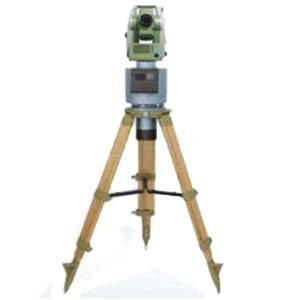
The gyro theodolite is a measuring instrument used to determine the true north azimuth angle. It mainly consists of a gyroscope and a theodolite. The gyroscope uses its own physical properties, such as axiality and precession, to be sensitive to the horizontal component of the earth's rotation angular velocity, thereby determining the true north azimuth angle. This instrument is widely used in fields such as mine surveying, engineering surveying, and military surveying and mapping. It is also an important supporting equipment for radar antenna orientation, UAV flight orientation, artillery and remote weapon launch orientation. Next we will propose some methods to improve the directional efficiency of gyro theodolite.


1.Factors affecting the directional efficiency of gyro theodolite

1) It takes a long time to measure the instrument constants before and after orientation, which is even more troublesome when the weather is bad. According to the requirements of the regulations, it is necessary to compare with the known sides twice before and after orientation to determine the instrument constants. Normally, two walking and directional measurements take half a day.

2) Directional measurement requires multiple measurement rounds. For example, using a 15~20s instrument requires 4 measurement rounds. The purpose is to improve accuracy and avoid errors, which usually takes 2h.

3) The final directional measurement results cannot be obtained at this time. Because the final orientation result cannot be obtained until a series of in-house calculations such as post-measurement constants, meridian convergence angles, and coordinate azimuth angles are completed, it takes two visits to the site to complete the subsequent measurement work of the orientation, such as accurately specifying the orientation. .

4) Some gyro theodolite or automatic gyro theodolite require a long waiting time. Some instruments need to pre-suspend the gyroscope in order to obtain more stable readings and reduce rework. This time is from tens of minutes to 1 hour;

5) When the instrument comes from the cold ground to the well, it will fog up and it will take 0.5 hours for the water vapor to dry.

6) Windproof treatment at the directional measurement site or organize and coordinate the shutdown of other work on site. This is because manual gyro theodolite cannot work in wind and vibration environments. This is because the manual gyro theodolite cannot work in an environment with wind and vibration. The nutation of the gyro indicator line often causes orientation errors to exceed limits and rework. It takes more time to coordinate and solve this problem.

7) Gyro-theodolite or high-precision automatic gyro theodolite can only solve the orientation problem. Actual surveying work often requires the completion of other measurements such as positioning, orientation, and stakeout at the same time. Usually, other instruments and personnel are required, and even need to be carried out again. In this way, the total man-time consumption is even more.

It can be seen that under normal circumstances without rework, one orientation takes about 5 to 8 hours. What takes more time is constant measurement, waiting before testing, multiple test orientations, etc. To improve efficiency, these problems should mainly be solved.


2.Methods to improve the orientation efficiency of gyro theodolite

There are many ways to improve the directional efficiency of a gyro theodolite. Here are some suggestions:


  1. Automation and intelligence: With the development of technology, realizing the automation and intelligence of gyro theodolite is the key to improving the orientation efficiency. By introducing automated control systems and artificial intelligence technology, manual intervention can be reduced and measurement accuracy and efficiency improved.
  2. Optimize data processing algorithms: Improve data processing algorithms, reduce data processing time and errors, and improve orientation efficiency. For example, introduce efficient filtering algorithms, optimize data fitting methods, etc.
  3. Strengthen instrument maintenance and calibration: Regularly maintain and calibrate the gyro-theodolite to ensure that the instrument is in good working condition. This can reduce instrument errors and improve measurement accuracy and efficiency.
  4. Improve the skill level of operators: Provide training and assessment to operators to improve their operating skills and familiarity with the instrument. This can reduce operating errors and improve orientation efficiency.
  5. Optimize the observation plan: Choose an appropriate observation plan based on the actual situation, such as selecting the appropriate observation time, optimizing the observation location, etc. This can improve the accuracy and efficiency of observations.
  6. Utilize modern communication technology: The introduction of modern communication technology, such as remote data transmission, real-time data processing, etc., can reduce data transmission and processing time and improve orientation efficiency.
  7. Integrated multi-sensor technology: Integrating the gyro theodolite with other sensors (such as GPS, accelerometer, etc.) can further improve orientation accuracy and efficiency.
  8. Develop new gyro theodolite: Continuously develop new gyro theodolite to improve its measurement accuracy, stability and automation, thereby further improving orientation efficiency.


Summarize

Improving the orientation efficiency of gyro theodolite can be achieved through automation and intelligence, as well as optimizing data processing methods. The gyro theodolite developed by our company not only uses the above-mentioned technology to improve its directional accuracy in the directional navigation function, but more importantly, our company's gyro theodolite has higher directional accuracy. For example, ER-GT-02 is ultra-high precision. Gyro theodolite has the following features:


  1. Orientation accuracy ≤3.6" (1σ);
  2. Strong pit interference capability, integrated body design, compact structure and stable performance;
  3. It has the functions of low position locking, automatic zero adjustment and observation, etc.

If you want to know more product knowledge about gyro theodolite, please contact our professional technical staff.

Precision Analysis of Fiber Optic Gyro Engineering Structure Deformation Detection


1 Method of engineering structure deformation detection based on fiber optic gyroscope

The principle of the engineering structure deformation detection method based on fiber optic gyro is to fix the fiber optic gyro to the detection device, measure the angular velocity of the detection system when running on the measured surface of the engineering structure, measure the operating distance of the detection device, and calculate the operating trajectory of the detection device to realize the detection of engineering structure deformation. This method is referred to as the trajectory method in this paper. This method can be described as "two-dimensional plane navigation", that is, the position of the carrier is solved in the plumb surface of the measured structure surface, and the trajectory of the carrier along the measured structure surface is finally obtained.

According to the principle of trajectory method, its main error sources include reference error, distance measurement error and Angle measurement error. The reference error refers to the measurement error of the initial inclination Angle θ0, the distance measurement error refers to the measurement error of ΔLi, and the Angle measurement error refers to the measurement error of Δθi, which is mainly caused by the measurement error of the angular velocity of the fiber optic gyroscope. This paper does not consider the influence of reference error and distance measurement error on the deformation detection error, only the deformation detection error caused by the fiber optic gyroscope error is analyzed.

2 Analysis of deformation detection accuracy based on fiber optic gyroscope

2.1 Error modeling of fiber optic gyroscope in deformation detection applications

Fiber optic gyro is a sensor for measuring angular velocity based on Sagnac effect. After the light emitted by the light source passes through the Y-waveguide, two beams of light rotating in opposite directions in the fiber ring are formed. When the carrier rotates relative to the inertial space, there is an optical path difference between the two beams of light, and the optical interference signal related to the rotational angular speed can be detected at the detector end, so as to measure the diagonal speed.
The mathematical expression of the fiber optic gyro output signal is: F=Kw+B0+V. Where F is the gyro output, K is the scale factor, and ω is the gyro
The angular velocity input on the sensitive axis, B0 is the gyroscopic zero bias, υ is the integrated error term, including white noise and slowly varying components caused by various noises with long correlation time, υ can also be regarded as the error of zero bias.
The sources of measurement error of fiber optic gyroscope include scale factor error and zero deviation error. At present, the scale factor error of the fiber optic gyroscope applied in engineering is 10-5~10-6. In the application of deformation detection, the angular velocity input is small, and the measurement error caused by the scale factor error is much smaller than that caused by the zero deviation error, which can be ignored. The DC component of the zero-bias error is characterized by the zero-bias repeatability Br, which is the standard deviation of the zero-bias value in multiple tests. The AC component is characterized by zero bias stability Bs, which is the standard deviation of the gyroscope output value from its mean in one test, and its value is related to the sampling time of the gyroscope.

2.2 Calculation of deformation error based on fiber optic gyroscope

Taking the simple supported beam model as an example, the error of deformation detection is calculated, and the theoretical model of structural deformation is established. On this basis, the detection is set
Based on the operating speed and sampling time of the system, the theoretical angular velocity of the fiber optic gyro can be obtained. Then the angular velocity measurement error of the fiber optic gyro can be simulated according to the zero deviation error model of the fiber optic gyro established above.

2.3 Example simulation calculation

The simulation setting of running speed and sampling time adopts a range-varying mode, that is, the ΔLi passed by each sampling time is fixed, and the sampling time of the same line segment is changed by changing the running speed. For example, when the ΔLi is 1 mm, such as the running speed is 2 m/s, the sampling time is 0.5 ms. If the operating speed is 0.1 m/s, the sampling time is 10 ms.

3 Relationship between fiber optic gyroscope performance and deformation measurement error

Firstly, the effect of zero-bias repeatability error is analyzed. When there is no zero bias stability error, the angular velocity measurement error caused by zero bias error is fixed, such as the faster the motion speed, the shorter the total measurement time, the smaller the impact of zero bias error, the smaller the deformation measurement error. When the running speed is fast, the zero bias stability error is the main factor causing the system measurement error. When the running speed is low, the zero bias repeatability error becomes the main source of the system measurement error.
Using typical medium precision fiber optic gyro index, that is, zero bias stability is 0.5 °/h when sampling time is 1 s, Zero repeatability is 0.05 °/h. Compare the system measurement errors at the operating speed of 2 m/s, 1 m/s, 0.2 m/s, 0.1 m/s, 0.02 m/s, 0.01 m/s, 0.002 m/s and 0.001 m/s. When the operating speed is 2 m/s, The measurement error is 8.514μm (RMS), when the measurement speed is reduced to 0.2m /s, the measurement error is 34.089μm (RMS), when the measurement speed is reduced to 0.002m /s, the measurement error is 2246.222μm (RMS), as can be seen from the comparison results. The faster the running speed, the smaller the measuring error. Considering the convenience of engineering operation, the running speed of 2 m/s can achieve better than 10 μm measurement accuracy.

4 Summary

Based on the simulation analysis of the engineering structure deformation measurement based on fiber optic gyro, the error model of fiber optic gyro is established, and the relationship between the deformation measurement error and the performance of fiber optic gyro is obtained by using the simple supported beam model as an example. The simulation results show that the faster the system runs, that is, the shorter the sampling time of the fiber optic gyroscope, the higher the deformation measurement accuracy of the system when the sampling number is unchanged and the distance detection accuracy is guaranteed. With the typical medium precision fiber optic gyro index and the running speed of 2 m/s, the deformation measurement accuracy of better than 10 μm can be achieved.
Ericco's ER-FOG-851 has a diameter of 78.5mm and an accuracy of ≤0.05 ~ 0.1º/h. ER-FOG-910 precision 0.02º/h, belongs to the high tactical level of the fiber optic gyroscope, our company produced gyroscope with small size, light weight, low power consumption, fast start, simple operation, easy to use and other characteristics, widely used in INS, IMU, positioning system, north finding system, platform stability and other fields. If you are interested in our fiber optic gyro, please feel free to contact us.

Monday, April 29, 2024

Analysis of Main Performance Parameters of Fiber Optic Gyroscope


1.Fiber Optic Gyroscope

When measuring the rotation and direction of aircraft and other moving objects, the accuracy of fiber optic gyroscopes is inherently limited by using ordinary classical optical methods.
The phase difference measurement accuracy of fiber optic gyroscope determines the overall precision of rotation measurement. The accuracy of fiber optic gyro is limited by many noise sources, and the main influence factor is shot noise. The quantization of photons produces shot noise. When a single photon passes through a device, its discrete nature means that the flow is not perfectly smooth, resulting in white noise. While it is possible to reduce shot noise by increasing the power (the rate at which photons pass through), the greater the power, the greater the other noise, so there is a trade-off.
At present, due to the low power of the detectors used, the new fiber optic gyroscopes do not yet pose a threat to commercial (classical) fiber optic gyros. The researchers expect that as detector technology advances and photon source brightness increases, entangled photon fiber gyroscopes will be commercially available in the near future. Overall, physicists hope that the current results represent a first step toward pushing the ultimate limits of sensitivity in fiber-optic gyroscopes.
The realization of the fiber optic gyroscope is mainly based on the theory of Segnick: when the light beam travels in a circular channel, if the circular channel itself has a rotational speed, then the time required for the light to travel along the direction of rotation of the channel is more than the time required to travel along the opposite direction of the channel.

2. Main performance parameters of fiber optic gyroscope

Through the above introduction, we must have a preliminary understanding of the fiber optic gyro. In this part, we mainly understand some of the main performance parameters of fiber optic gyroscopes.

2.1 Zero bias and zero drift

Zero bias is the output of the gyroscope when the input angular velocity is zero (i.e. the gyroscope is at rest), expressed as the equivalent input angular velocity corresponding to the average output value measured within a specified time, ideally the component of the Earth's rotation angular velocity. Zero drift is zero bias stability, indicating the degree of dispersion of the gyroscope output around its zero bias mean when the input angular rate is zero, expressed by the equivalent input angular rate corresponding to the standard deviation of the output in a specified time. Zero drift is the most important and basic index to measure the accuracy of FOG(fiber optic gyro). The main factor of zero drift is the non-reciprocal phase shift error introduced in the fiber coil by the ambient temperature variation. In order to stabilize zero drift, temperature control or temperature compensation of IFOG is often required. In addition, polarization will also have a certain influence on zero drift. In IFOG, polarization filtering and polarization-maintaining fiber are often used to eliminate the influence of polarization on zero drift.

2.2 Scale factor

Scale factor is the ratio of the output of the gyroscope to the input angular rate, which can be expressed by a specific linear slope on the coordinate axis. It is an index reflecting the sensitivity of the gyroscope, and its stability and accuracy are an important index of the gyroscope, comprehensively reflecting the test and fitting accuracy of the fiber optic gyro. The stability of the scale factor is dimensionless and is usually expressed in parts per million (ppm). The error of the scale factor mainly comes from the temperature change and the instability of the polarization state of the fiber.

2.3 Random walk coefficient

A technical index to characterize the white noise of the angular velocity output in a fiber optic gyro, it reflects the uncertainty of the angular velocity integral of the fiber optic gyro output over time, so it can also be called an angular random walk. The random walk coefficient reflects the development level of the gyroscope, and also reflects the minimum detectable angular rate of the gyroscope. The error is mainly due to random spontaneous emission of photons, noise and mechanical jitter introduced by photodetector and digital circuit.

2.4 Threshold and resolution

The threshold indicates the minimum input rate that a fiber optic gyro can sense. Resolution represents the minimum input rate increment that a gyroscope can sense at a specified input angular rate. Both threshold and resolution characterize the sensitivity of a fiber optic gyroscope.

2.5 Maximum input angular speed

Represents the maximum input rate of the gyroscope in the positive and negative directions, and represents the dynamic range of the gyroscope, that is, the rate range of the fiber optic gyro can be induced.

3.Summary

When choosing a fiber optic gyros, we mainly look at its zero bias stability, zero bias repeatability, measurement range, etc., such as our Ericco fiber optic gyro ER-FOG-50, its measurement range is -500~500, zero bias stability is 0.2~2.0º/h, zero bias repeatability and zero bias stability are consistent. ER-FOG-60, its measuring range is -1000~+1000, zero bias stability is 0.06~0.5º/h, compared with the ER-FOG-60 measurement range is large, the accuracy is relatively high, of course, we have a variety of medium precision fiber optic gyro models, mainly according to your application scenario to decide. If you are interested in our fiber optic gyro, please feel free to contact us.


High-precision IMU is coming to help in the fields of land, sea and air

  High-precision IMU is now widely used in many fields of sea, land and air. It can provide real-time and accurate information on the carrie...