Tuesday, June 11, 2024

Why is it Called Fiber Optic Gyroscope?

 Like ring laser gyro, fiber optic gyro has the advantages of no mechanical moving parts, no preheating time, insensitive acceleration, wide dynamic range, digital output and small size. In addition, fiber optic gyro also overcomes the fatal shortcomings of ring laser gyro such as high cost and blocking phenomenon.

Fiber optic gyro is a kind of optical fiber sensor used in inertial navigation.
Because it has no moving parts - high-speed rotor, called solid state gyroscope. This new all-solid gyroscope will become the leading product in the future and has a wide range of development prospects and application prospects.

1. Fiber optic gyro classification

According to the working principle, fiber optic gyroscope can be divided into interferometric fiber optic gyro (I-FOG), resonant fiber optic gyro (R-FOG) and stimulated Brillouin scattering fiber optic gyroscope (B-FOG). At present, the most mature fiber optic gyro is the interferometric fiber optic gyroscope (that is, the first generation of fiber optic gyroscope), which is the most widely used. It uses multi-turn optical fiber coil to enhance SAGNAC effect. A double-beam ring interferometer composed of multi-turn single-mode optical fiber coil can provide high accuracy, but also will inevitably make the overall structure more complicated.
Fiber optic gyros are divided into open ring fiber optic gyroscopes and closed loop fiber optic gyros according to the type of loop. Open-loop fiber optic gyro without feedback, directly detect the optical output, save many complex optical and circuit structure, has the advantages of simple structure, cheap price, high reliability, low power consumption, the disadvantage is the input-output linearity is poor, small dynamic range, mainly used as an Angle sensor. The basic structure of an open-loop interferometric fiber optic gyro is a ring dual-beam interferometer. It is mainly used for occasions where the accuracy is not high and the volume is small.

2. Status and future of fiber optic gyroscope

With the rapid development of fiber optic gyro, many large companies, especially military equipment companies, have invested huge financial resources to study it. The main research companies for the United States, Japan, Germany, France, Italy, Russia, low and medium precision gyroscope has completed the industrialization, and the United States has maintained a leading position in this area of research.
The development of fiber optic gyroscope is still at a relatively backward level in our country. According to the level of development, the gyro development is divided into three echelons: the first echelon is the United States, the United Kingdom, France, they have all the gyro and inertial navigation research and development capabilities; The second tier is mainly Japan, Germany, Russia; China is currently in the third tier. The research of fiber optic gyro in China started relatively late, but with the efforts of the majority of scientific researchers, it has gradually narrowed the gap between us and the developed countries.
At present, China's fiber optic gyro industry chain is complete, and manufacturers can be found upstream and downstream of the industry chain, and the development accuracy of fiber optic gyro has reached the requirements of middle and low accuracy of inertial navigation system. Although the performance is relatively poor, it will not bottleneck like the chip.
The future development of fiber optic gyro will focus on the following aspects:
(1) High precision. Higher precision is an inevitable requirement for fiber optic gyro to replace laser gyro in advanced navigation. At present, the high precision fiber optic gyro technology is not fully mature.
(2) High stability and anti-interference. Long-term high stability is also one of the development directions of fiber optic gyroscope, which can maintain navigation accuracy for a long time under harsh environment is the requirement of inertial navigation system for gyroscope. For example, in the case of high temperature, strong earthquake, strong magnetic field, etc., the fiber optic gyro must also have sufficient accuracy to meet the requirements of users.
(3) Product diversification. It is necessary to develop products with different precision and different needs. Different users have different requirements for navigation accuracy, and the structure of the fiber optic gyro is simple, and only the length and diameter of the coil need to be adjusted when changing the accuracy. In this respect, it has the advantage of surpassing mechanical gyro and laser gyro, and its different precision products are easier to achieve, which is the inevitable requirement of the practical application of fiber optic gyro.
(4) Production scale. The reduction of cost is also one of the preconditions for fiber optic gyro to be accepted by users. The production scale of various components can effectively promote the reduction of production costs, especially for middle and low precision fiber optic gyro.

3.Summary

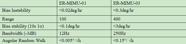
The accuracy of the fiber optic gyroscope ER-FOG-50 is 0.2~2.0º/h, and the accuracy of the ER-FOG-60 is 0.06~0.5º/h. Their application fields are basically the same, and can be used in small IMU, INS, missile seeker servo tracking, photoelectric pod, UAV and other application fields. If you want more technical data, please feel free to contact us.

Tuesday, June 4, 2024

Do You Know Minimum FOG IMU?


ER-FIMU-50 FOG IMU is a minimum cost-effective inertial measurement device for navigation, control and dynamic measurement. The system adopts high reliability closed-loop

hashtagfiber optic gyroscope and hashtagaccelerometer, and ensures the measurement accuracy through multiple compensation techniques.

Applications

hashtagAHRS
Guidance control system
Vehicle and ship attitude measurement
Inertial/satellite hashtagintegrated hashtagnavigation hashtagsystem
Drilling system
Mobile mapping system
Satellite communication in motion

Wednesday, May 29, 2024

Navigation grade MEMS IMU VS Tactical grade MEME IMU


Introduce

Navigation-grade IMU and tactical-grade IMU are different levels of inertial measurement units (IMU). They have significant differences in accuracy, performance and application scenarios. Navigation-level and tactical-level IMU will be introduced below.


Navigation grade MEMS IMU

First of all, navigation-grade IMU is mainly used for general navigation and positioning tasks, and its performance requirements are relatively low. It usually has high accuracy and reliability and can meet the needs of most navigation applications. Through internal sensors such as accelerometers and gyroscopes, the navigation-grade IMU can accurately measure key information such as the acceleration, angular velocity, and direction of objects. After processing, this information can be used to achieve precise positioning and navigation functions, thereby improving driving safety and stability.


Tactical Grade MEMS IMU

Tactical-grade IMU have some unique core features. For example, they are able to operate gyroscopes with extremely low bias stability, meaning that bias errors become more stable over time. This stability is critical for high-precision applications such as drone navigation. And for higher-precision applications, such as drone navigation, antenna and weapon platform stabilization, tactical-grade IMU are required. Gyroscopes are known to operate with extremely low bias stability, meaning their bias errors remain relatively stable over time. This feature allows tactical-grade IMU to maintain excellent performance in long-term, high-precision applications. In addition, tactical-grade IMU are usually equipped with high-quality MEMS accelerometers and gyroscopes to provide more accurate data output.


It can be seen that navigation-grade IMU and tactical-grade IMU have different emphasis on accuracy, performance and application scenarios. When selecting an IMU, the most appropriate level needs to be determined based on specific application requirements. The following will briefly describe the differences between navigation-grade MEMS IMU and tactical-grade MEMS IMU, and introduce two IMU from the domestic inertial navigation company ERICCO.


Navigation grade MEMS IMU VS Tactical grade MEMS IMU

There are significant differences in performance and application between navigation-grade IMU and tactical-grade IMU.


First of all, navigation-grade IMU are usually used in scenarios that require relatively low accuracy, and their performance and accuracy may not be as good as tactical-grade IMU. Secondly, tactical-grade IMU offer higher performance and accuracy, making them the first choice for demanding applications such as drone navigation. These IMUs operate gyroscopes with extremely low bias stability, which means the bias error becomes more stable over time. This characteristic is essential for mission-critical and high-precision applications such as drone navigation, antenna and weapon platform stabilization.


ERICCO is an inertial navigation company that independently develops MEMS IMU. The MERMS IMU it develops are mainly divided into navigation level and tactical level. The following are the company's ER-MIMU-01 (navigation level) and ER-MIMU-03 (tactical level). Level) built-in MEMS gyroscope specification comparison:

ER-MIMU-01ER-MIMU-03
Bias Instability<0.02deg/hr<0.3deg/hr
Range100400
Bias stability (10s 1σ)<0.1deg/hr<3deg/hr
Bandwidth (-3dB)12Hz250Hz
Angular Random Walk<0.005°/√h<0.15°/ √h


It can be seen from the above table that the accuracy of the built-in gyroscope of the navigation-grade MEMS IMU is much higher than that of the tactical-grade one, especially the bias instability of the navigation-grade one is 0.02, and the tactical-grade one is 0.3. The accuracy is much higher. ER-MIMU-03 has a larger range than ER-MIMU-01.

Summarize

Navigation-grade IMU and tactical-grade IMU are different in accuracy, stability and applicable scenarios. When selecting, the most appropriate IMU type needs to be determined based on specific application requirements. For more professional information, please consult our relevant personnel.

Tuesday, May 21, 2024

Measurement Error and Calibration of FOG IMU


1. What causes FOG IMU measurement errors?

Inertial measurement unit is the core component of navigation information and heading attitude reference system, which determines the accuracy and environmental adaptability of the system. Fiber optic gyro is a kind of photoelectric inertial sensor based on Sagnac effect. It has the advantages of high precision, strong resistance to vibration and shock, fast start, etc. It is an ideal angular velocity sensor for rotorcraft, high performance navigation information and heading attitude measurement system. FOG's adaptability to temperature environment is poor, and the dynamic temperature environment in the working process of rotorcraft is harsh, which leads to the measurement error of FOG inertial measurement unit. It is necessary to study the precise calibration compensation method of FOG inertial measurement unit error to improve its environmental adaptability and measurement accuracy.

2. Calibration method 

Traditional IMU calibration methods include static multi-position calibration under normal temperature environment, angular rate calibration and hybrid calibration, etc. Among them, static multi-position calibration method can calibrate the error coefficient of IMU acceleration channel with high precision, but due to the small Earth rotation rate, The precision of the small FOG used in the high performance navigation information and heading attitude measurement system of the rotorcraft is similar to the earth rotation rate, resulting in low calibration accuracy of the error coefficient of the angular velocity channel. The error coefficient of FOG IMU angular velocity channel can be accurately calibrated by the traditional simple angular velocity calibration method, but the error coefficient of acceleration channel cannot be accurately calibrated. How to further reduce the calibration workload and improve the calibration accuracy is the key technology to be solved by FOG inertial measurement unit. In addition, parameters calibrated at room temperature will reduce FOG inertial measurement unit measurement accuracy if applied at high or low temperatures. Methods such as least squares fitting are often used to compensate the zero-bias or scale-factor temperature errors of inertial devices. Among them, the high-order least squares fitting compensation method can improve the system accuracy, but significantly increase the calculation amount of real-time compensation. The one-time fitting method has a small calculation amount, but it cannot meet the actual compensation accuracy requirements. Therefore, it is another key problem for FOG inertial measurement unit, a high performance and reliable navigation information and heading attitude measurement system of rotorcraft, to study the compensation method with small amount of computation and high precision.
Based on the FOG inertial measurement unit integrated error modeling in the high performance navigation information and heading attitude measurement system of rotorcraft, we calibrate and compensate the temperature and dynamic errors of the small low-precision FOG inertial measurement unit system, and propose a FOG inertial measurement unit full temperature tripartite positive and negative rate/position calibration method and piecewise linear interpolation compensation method for temperature errors. A tripartite positive and negative speed/one position calibration scheme is designed at each constant temperature point, and piecewise linear interpolation method is used to compensate the zero deviation of angular velocity channel, zero deviation of acceleration channel and scale factor temperature errors. The vehicle-mounted experiments show that the method can improve the system's environmental adaptability and measurement precision significantly, which lays a foundation for the further development of a small and high-performance fiber optic gyro IMU aircraft navigation information and heading attitude reference system.

3.FOG IMU deterministic error modeling

3.1 Angular velocity channel error model

FOG inertial measurement unit in rotorcraft, high performance navigation information and heading attitude measurement system consists of three fiber optic gyroscopes and accelerometers, IMU structure and data acquisition and preprocessing module. Three domestic small low-precision 11-FA fiber optic gyroscope sensitive carrier external input angular velocity, three GJ-27 quartz flexible accelerometers sensitive carrier external linear acceleration. FOG is insensitive to g and g2 terms. Considering the installation error, scale factor error and zero bias error of FOG IMU, the angular velocity channel error model of FOG inertial measurement unit in northeast sky coordinate system is established as

FOG IMU angular velocity channel model formula

Where, i is the output angular velocity of FOG inertial measurement unit i axial gyro, and i is the input angular velocity of i axial gyro. i is zero deviation of i axis gyroscope; Ki is the scale factor of i axial gyroscope; Eij is the installation error coefficient of the angular velocity channel, and i and j are collectively referred to as the coordinate axes X, Y and Z.

3.2 Acceleration channel error model

FOG IMU acceleration channel error model is:

FOG IMU acceleration channel model formula

Where, ai is the output of FOG inertial measurement unit i axial addition, ai is the input of i axial addition,  i is zero deviation of i axial addition, Kai is the scale factor of i axial addition, Mij is the installation error coefficient of acceleration channel.

3.3 Full temperature tripartite positive/negative speed/one position calibration

The precision of inertial devices in FOG IMU is mainly related to external environment mechanics and temperature excitation. The operating environment temperature of rotorcraft varies greatly with the different seasons and flight altitudes. Due to the large random dynamic disturbance caused by wind gust and turbulence during successive flights, the influence of different temperatures and dynamic environment on FOG inertial measurement unit accuracy is mainly studied. The calibration temperature range, temperature point distribution density and calibration dynamic range are set according to the actual working environment and accuracy requirements of the system.
According to the mathematical model of system error, a FOG inertial measurement unit tripartite positive and negative rate/one position error calibration method is designed based on a temperature-controlled single-axis speed turntable without pointing north and a high-precision hexahedron tool. As shown in Figure 1, the hexahedron tooling is turned three times at each calibrated temperature point to ensure that the X, Y, and Z axes of FOG inertial measurement unit and the ZT axis of the turntable are reconnected respectively. According to the dynamic environment of the system, set the turntable in each direction to calibrate the positive and negative speed, and ensure that the rotation is above 360° at the speed point.

Tripartite rate-forward and rate-position calibration scheme

4. Full temperature piecewise linear interpolation compensation

In order to solve the problem of using FOG IMU in the navigation information and heading attitude measurement system of rotorcraft with high performance and small amount of computation and high precision error compensation, we use the segmented low-order linear interpolation method, dividing the interpolation interval into several cells, and using linear interpolation polynomial on each cell. It can be seen that the FOG inertial measurement unit angular velocity channel and acceleration channel zero bias, scale factor temperature error piecework linear interpolation compensation algorithm of rotor aircraft operating environment are between -10℃ and 40℃, so the calibration temperature points are set as -10℃, 5℃, 20℃, 30℃ and 40℃ respectively. The FOG inertial measurement unit is installed in the center of the hexahedron tool, and the X, Y and Z axes of the inertial navigation system are respectively parallel to the datum normal of the hexahedron tool through the high-precision positioning table. Then the hexahedral tooling is fixed horizontally on the plane of the temperature controlled single-axis rate turntable. The three-bit positive and negative speed/one-position calibration as shown in Figure 1 was realized by flipping the hexahedron tooling. Then change the temperature setting value, according to the above method, carry out the calibration experiment at -10℃, 5℃, 20℃, 30 ℃, 40 ℃ in turn.

5. Summary

FOG IMU is the core component of the navigation information and heading attitude reference system of small rotorcraft. ericco's ER-FIMU-50 and ER-FIMU-70, we can use full-temperature three-way positive and negative rate/one position calibration and PLI compensation method. According to the error characteristics of fiber optic gyro and quartz flexible accelerometer, the FOG inertial measurement unit error model is established, and the three-bit positive and negative rate/one-position calibration scheme is designed at each constant temperature point. The PLI algorithm is used to compensate the zero bias and scale factor temperature errors of the system in real time, reducing the calibration workload and the calculation amount of the compensation algorithm, and improving the system dynamics, temperature environment adaptability and measurement accuracy.

Monday, May 20, 2024

What can a Tilt Sensor be Used for?


Classification of angles

Angle measurement is an important part of geometric measurement. Plane angle according to the spatial position of the plane can be divided into: horizontal angle (or azimuth angle) in the horizontal plane, vertical right angle (or inclination angle) in the vertical plane, space angle is the synthesis of horizontal angle and vertical right angle; According to the range can be divided into circular indexing angle and small angle; According to the nominal value can be divided into fixed angle and arbitrary angle; According to the component unit can be divided into line angle and plane angle; According to the formation method, it can be divided into fixed angle and dynamic angle. Fixed angle refers to the angle of components processed or assembled, and the angular position of the instrument when it is restored to static state after rotation. Dynamic angle refers to the angle of the object or system in the process of motion, such as the angle of the satellite orbit to the earth's equatorial plane, the axis angle drift when the spindle of the precision equipment rotates, and the real-time angle signal output when the angle measuring equipment moves at a certain angular speed and angular acceleration.

What is another name for a tilt sensor

Tilt sensor is also known as the inclinometer, inclination sensor, level inclinometer, often used in the measurement of the horizontal angle change of the system, the level from the simple bubble level in the past to the electronic level is the result of the development of automation and electronic measurement technology. As a testing tool, it has become an indispensable and important measuring tool in bridge construction, railway laying, civil engineering, oil drilling, aviation and navigation, industrial automation, intelligent platform, mechanical processing and other fields. Electronic level is a very accurate measuring small angle detection tool, it can be used to measure the inclination of the measured plane relative to the horizontal position, the degree of parallelism between the two components and the degree of perpendicularity.

The basic principle of tilt sensor (inclinometer)

how does tilt sensor works

The theory is based on Newton's second law: according to the basic principles of physics, inside a system, velocity cannot be measured, but acceleration can be measured. If the initial speed is known, the line speed can be calculated by integrating, and then the linear displacement can be calculated, so it is actually an acceleration sensor using the principle of inertia. When the tilt sensor is at rest, that is, there is no acceleration in the side and vertical directions, then the only force acting on it is the acceleration of gravity. The angle between the vertical axis of gravity and the sensitive axis of the acceleration sensor is the angle of inclination. The tilt sensor in the general sense is static measurement or quasi-static measurement, once there is external acceleration, then the acceleration measured by the acceleration chip contains the external acceleration, so the calculated angle is not accurate, therefore, the common practice is to increase the mems gyro chip, and adopt the preferred Kalman filter algorithm. The ER-TS-3260VO's built-in (MEMS) solid pendulum can measure changes in the static gravity field, convert them into changes in inclination, and output them through voltage (0~10V, 0~5V optional), so that the calculated angle is quite accurate.

Use

Tilt sensors are used in a variety of applications to measure angles. For example, high-precision laser instrument level, engineering machinery equipment leveling, long-distance ranging instruments, high-altitude platform safety protection, orientation satellite communication antenna elevation measurement, ship navigation attitude measurement, shield pipe application, dam detection, geological equipment tilt monitoring, artillery barrel initial launch angle measurement, radar vehicle platform detection, satellite communication vehicle attitude detection and so on.

Application example

Used in tower cranes

The inclination sensor is the main part of the anti-overturning monitoring instrument of tower crane. The function of the inclination sensor is to measure the angle of the tower tilt in real time. Since the tilt angle at the top of the tower is very small, the sampling frequency of the tilt sensor should be within the range of 0.5-10Hz, the measurement accuracy is higher than 0.05 degrees, and the noise caused by the vibration of the tower should be filtered out to ensure reliable communication and accurate judgment. The accuracy of the ER-TS-3160VO Voltage Single Axis Tilt Meter is 0.01 degrees, which is obviously higher than 0.05 degrees, and it is suitable for the tilt monitoring in this case.

Friday, May 17, 2024

Navigation grade MEMS IMU VS Tactical grade MEME IMU

 Introduce

Navigation-grade IMU and tactical-grade IMU are different levels of inertial measurement units (IMU). They have significant differences in accuracy, performance and application scenarios. Navigation-level and tactical-level IMU will be introduced below.

Navigation grade MEMS IMU

First of all, navigation-grade IMU is mainly used for general navigation and positioning tasks, and its performance requirements are relatively low. It usually has high accuracy and reliability and can meet the needs of most navigation applications. Through internal sensors such as accelerometers and gyroscopes, the navigation-grade IMU can accurately measure key information such as the acceleration, angular velocity, and direction of objects. After processing, this information can be used to achieve precise positioning and navigation functions, thereby improving driving safety and stability.

Tactical Grade MEMS IMU

Tactical-grade IMU have some unique core features. For example, they are able to operate gyroscopes with extremely low bias stability, meaning that bias errors become more stable over time. This stability is critical for high-precision applications such as drone navigation. And for higher-precision applications, such as drone navigation, antenna and weapon platform stabilization, tactical-grade IMU are required. Gyroscopes are known to operate with extremely low bias stability, meaning their bias errors remain relatively stable over time. This feature allows tactical-grade IMU to maintain excellent performance in long-term, high-precision applications. In addition, tactical-grade IMU are usually equipped with high-quality MEMS accelerometers and gyroscopes to provide more accurate data output.

It can be seen that navigation-grade IMU and tactical-grade IMU have different emphasis on accuracy, performance and application scenarios. When selecting an IMU, the most appropriate level needs to be determined based on specific application requirements. The following will briefly describe the differences between navigation-grade MEMS IMU and tactical-grade MEMS IMU, and introduce two IMU from the domestic inertial navigation company ERICCO.

Navigation grade MEMS IMU VS Tactical grade MEMS IMU

There are significant differences in performance and application between navigation-grade IMU and tactical-grade IMU.

First of all, navigation-grade IMU are usually used in scenarios that require relatively low accuracy, and their performance and accuracy may not be as good as tactical-grade IMU. Secondly, tactical-grade IMU offer higher performance and accuracy, making them the first choice for demanding applications such as drone navigation. These IMUs operate gyroscopes with extremely low bias stability, which means the bias error becomes more stable over time. This characteristic is essential for mission-critical and high-precision applications such as drone navigation, antenna and weapon platform stabilization.

ERICCO is an inertial navigation company that independently develops MEMS IMU. The MERMS IMU it develops are mainly divided into navigation level and tactical level. The following are the company’s ER-MIMU-01 (navigation level) and ER-MIMU-03 (tactical level). Level) built-in MEMS gyroscope specification comparison : 

It can be seen from the above table that the accuracy of the built-in gyroscope of the navigation-grade MEMS IMU is much higher than that of the tactical-grade one, especially the bias instability of the navigation-grade one is 0.02, and the tactical-grade one is 0.3. The accuracy is much higher. ER-MIMU-03 has a larger range than ER-MIMU-01.

Summarize

Navigation-grade IMU and tactical-grade IMU are different in accuracy, stability and applicable scenarios. When selecting, the most appropriate IMU type needs to be determined based on specific application requirements. For more professional information, please consult our relevant personnel.

Email: info@ericcointernational.com
Wechat: 13992884879
WhatsApp: +8613992884879

website:https://www.ericcointernational.com/inertial-measurement-units

Wednesday, May 15, 2024

Fiber Optic Gyroscopes for Inertial Navigation


1. What is inertial navigation

To understand what inertial navigation is, we first need to break the phrase into two parts, that is, navigation + inertia.
Navigation, in simple terms, solves the problem of getting from one place to another, indicating the direction, typically the compass.
Inertia, originally derived from Newtonian mechanics, refers to the property of an object that maintains its state of motion. It has the function of recording the motion state information of the object.
A simple example is used to illustrate inertial navigation. A child and a friend play a game at the entrance of a room covered with tiles, and walk on the tiles to the other side according to certain rules. One forward, three left, five front, two right... Each of his steps is the length of a floor tile, and people outside the room can get his complete motion trajectory by drawing the corresponding length and route on the paper. He doesn't need to see the room to know the child's position, speed, etc.
The basic principle of inertial navigation and some other types of navigation is pretty much like this: know your initial position, initial orientation (attitude), the direction and direction of movement at each moment, and push forward a little bit. Add these together (corresponding to the mathematical integration operation), and you can just get your orientation, position and other information.
So how to get the current orientation (attitude) and position information of the moving object? You need to use a lot of sensors, in inertial navigation is the use of inertial instruments: accelerometer + gyroscope.
Inertial navigation uses gyroscope and accelerometer to measure the angular velocity and acceleration of the carrier in the inertial reference frame, and integrates and calculates the time to obtain the velocity and relative position, and transforms it into the navigation coordinate system, so that the carrier's current position can be obtained by combining the initial position information.
Inertial navigation is an internal closed loop navigation system, and there is no external data input to correct the error during the carrier movement. Therefore, a single inertial navigation system can only be used for short periods of navigation. For the system running for a long time, it is necessary to periodically correct the internal accumulated error by means of satellite navigation.

2. Gyroscopes in inertial navigation

Inertial navigation technology is widely used in aerospace, navigation satellite, UAV and other fields because of its high concealment and complete autonomous ability to obtain motion information. Especially in the fields of micro-drones and autonomous driving, inertial navigation technology can provide accurate direction and speed information, and can play an irreplaceable role in complex conditions or when other external auxiliary navigation signals fail to play the advantages of autonomous navigation in the environment to achieve reliable attitude and position measurement. As an important component in inertial navigation system, fiber optic gyro plays a decisive role in its navigation ability. At present, there are mainly fiber optic gyroscopes and MEMS gyroscopes on the market. Although the precision of the fiber optic gyroscope is high, its entire system is composed of couplers,
Modulator, optical fiber ring and other discrete components, resulting in large volume, high cost, in the micro UAV, unmanned and other fields can not meet the requirements for its miniaturization and low cost, the application is greatly limited. Although MEMS gyro can achieve miniaturization, its accuracy is low. In addition, it has moving parts, poor resistance to shock and vibration, and is difficult to apply in harsh environments.


3 Summary

Ericco's fiber optic gyroscope ER-FOG-851 is specially designed according to the concept of traditional fiber optic gyroscopes, with a small size of 78.5*78.5*35mm; Light weight, less than or equal to 300g; Low power consumption, less than or equal to 4W; Start fast, start time is only 5s; This fiber optic gyroscope easy to operate and easy to use, and is widely used in INS, IMU, positioning system, north finding system, platform stability and other fields.
The accuracy of our ER-FOG-851 is between 0.05 and 0.1, and the 851 is divided into ER-FOG-851D and ER-FOG-851H. The biggest difference between these two fiber optic gyroscope is that the measurement range is different, of course, the accuracy is different, and the measurement range of ER-FOG-851D is wider. The application range is naturally wider than the ER-FOG-851H. Our fiber optic gyroscope can be used in inertial navigation, you can make a detailed choice according to the accuracy value and measurement range, you are welcome to consult us at any time and get more technical data.


Range And Zero Bias Of Fiber Optic Gyroscope Er Fog 851

Choose a suitable IMU to make your drone flight more stable and safe

         As one of the core components of drones, IMU plays an irreplaceable role. Its high precision, fast response and freedom from extern...