Thursday, November 23, 2023

Tilt Sensors for Solar Photovoltaic Power Generation Tracking Systems


Tilt sensors are real-time measurements of the eye in solar photovoltaic tracking systems.

Solar power generation, divided into solar photovoltaic power generation and solar thermal power generation two, the current development of solar photovoltaic power generation faster, more rapid, is a rapid development of the field, currently China, the United States, Europe, Japan, India, Australia and other countries, the rapid development, Ericco has developed more than a dozen different types of tilt sensors for photovoltaic tracking systems to meet customers in different countries.

Solar photovoltaic tracking system composition:

1. Solar photovoltaic tracking system is generally composed of tilt sensor, motor, worm gear and controller. According to the specific application, solar photovoltaic tracking system is divided into horizontal single-axis photovoltaic tracking system, oblique single-axis photovoltaic tracking system, two-axis photovoltaic tracking system, which can not only comprehensively improve the power generation of the power station, but also adapt to local conditions, and better adapt to various complex terrain and application scenarios.

2. The solar photovoltaic tracking system needs to adjust the tilt angle of the solar photovoltaic panel, so that the solar photovoltaic panel can be adjusted in time according to the changes in the movement of the sun, so that the sun rays are always vertically illuminated on the solar photovoltaic panel to obtain the maximum solar radiation.

3. Although the angle of the sun varies widely during the day, the angle of the sun is almost constant at a certain time. The system can calculate the local sun's orientation and angle information every day of the year according to the local latitude and longitude, and the information is stored in the controller's software, so that the angle information of the photovoltaic panel measured by the inclination sensor can be compared with the angle information of the sun stored by the controller, and then the control motor can adjust the photovoltaic panel at that time for the best position.

4. The ER-TS-3160VO tilt sensor, as the eye of real-time measurement in the solar photovoltaic tracking system, is one of the key equipment to optimize the solar reception rate. The accuracy of the inclination sensor has certain requirements, Ericco self-developed inclination sensor is currently on the market has been mature application in a number of solar photovoltaic projects, the use of industrial devices stable performance, high reliability, and with anti-touch, anti-misconnection protection function, anti-wind sand, anti-salt spray anti-ultraviolet, Fully consider the complex application scenarios of solar photovoltaic.

If you want to learn more about MEMS tilt sensors or buy tilt sensors

Please contact me in the following ways:

Email: info@ericcointernational.com

Whatsapp: 173 9198 8506

The Role of Quartz Accelerometer in Surveying and Mapping Field


 With the completion of the construction of surveying and mapping equipment systems such as satellite navigation and positioning system platform, modern surveying and mapping reference system infrastructure, aerospace remote sensing image rapid acquisition platform, advanced field surveying and mapping technology and equipment, geographic information data processing technology and equipment, and geographic information data exchange and transmission service network, the surveying and mapping industry has entered the stage of information surveying and mapping.

High precision inertial system is an important support of information surveying and mapping system. Therefore, it is particularly important to select suitable high-precision equipment. The designed accelerometer not only meets the measurement requirements in terms of accuracy, but also has the characteristics of small size. For example, ER-QA-03A not only reaches 10-50μg in zero bias stability, but also can reach 10-30μg/g2 and 15-50 PPM in second-order nonlinearity and scale factor, respectively.

Geographic surveying and mapping technology plays a key role in geological exploration and resource exploitation. Through surface survey and underground exploration, the distribution of underground mineral resources and geological structure information can be obtained, which provides scientific basis for mineral exploration and resource development. Geological and geophysical survey is an important part of oil and gas exploration. These surveys provide valuable information about subsurface geology and help identify potential oil and gas resources.

The data acquisition methods of information surveying and mapping include traditional surveying, aerial photogrammetry, satellite remote sensing and liDAR surveying. In addition to traditional mapping methods, other modern mapping methods require the support of flight control systems or optical stabilization systems based on high-precision inertial measurement units, so that the vehicle can acquire clear images during the dynamic process. In order to ensure the collection of accurate data information, the accuracy and precision of the mapping equipment is critical. 

If you want to know more about quartz accelerometers or purchase, please contact me through the following ways:

Email : info@ericcointernational.com

Web:https://www.ericcointernational.com/accelerometer/quartz-accelerometer

Wednesday, November 22, 2023

Tilt Sensors for Tunnel Boring Machines


The tilt sensor is an important part of all parts of the full section tunnel boring machine. It can measure the tilt angle of the body of the shield machine and the tilt angle of the mining cavity, and calculate the distance of the mining deviation through a series of complex operations, which plays a very important role in correcting the guidance. 

In the past, the drilling and blasting method is widely used in mountain tunnel hard rock tunneling, but under the same conditions, the tunneling speed of the full section tunnel boring machine is about 8 times that of the drilling and blasting method, which has the advantages of high efficiency, fast, high quality, safety, economy and environmental protection.

The driving principle of hard rock tunnel boring machine is that the knife rotates and the pressure hob acts on the tunnel palm surface. The hob rotates on the palm surface to loosen the surrounding rock. The excavated stone slag is collected by the side scraper and enters the belt conveyor through the slag bucket, and then the belt conveyor transports the stone slag along the boring machine to the end, and finally the stone slag is loaded onto the slag truck for transport.

The slightest difference is a thousand miles, some tunnels are very long, and the small gap may be a trouble in the later period, so the accuracy of the tunnel boring machine is very high. Not only that, the tunnel environment is humid, the temperature difference is different, and the vibration of the tunnel boring machine is strong.

The ER-TS-3266DI tilt sensor produced by Ericco fully considers the above situation, especially optimized circuit protection and program protection in vibration resistance, so as not to make the sensor unable to work because of excessive vibration. After testing, the long-term stability reaches 0.05° and has a high resolution of 0.0025°, with IP67 waterproof grade, which can be used in underground humid environment, and the wide temperature working -40~+ 85°C can also meet most practical conditions. It can be seen that the ER-TS-3266DI tilt sensor produced by Ericco is competent for the role of the boring machine direction test control, and its performance parameters are as follows:

① Range +15°, +30°

② Wide voltage input 9~36V

③ Wide temperature operation -40~ +85°C

④ High vibration resistance>20000g

⑤ High resolution 0.0025°

⑥ Waterproof grade IP67, strong ability to resist external electromagnetic interference.

⑦ can be adjusted and set for vibration suppression on site.

If you want to learn more about MEMS tilt sensors or buy tilt sensors

Please contact me in the following ways:

Email: info@ericcointernational.com

Whatsapp: 173 9198 8506

What sensors are inside the IMU and how do they work?

Inertial measurement units typically consist of three different types of sensors. The first type of sensor is an accelerometer, which measures acceleration, or the rate at which an object accelerates or decelerates. While there are many different sensor technologies for accelerometers, by far the most common for wearable applications is MEMS (microelectromechanical systems). MEMS are sensor systems composed of electrical and mechanical components, typically etched from micron-sized silicon.

Whenever the MEMS accelerometer experiences acceleration, the proof mass also experiences that acceleration. An etched spring set resists this acceleration. Using Hooke’s law (spring force is proportional to the distance the spring is compressed) and Newton’s second law (force is proportional to acceleration), check that the distance a mass moves is proportional to the acceleration it experiences (see figure below). This movement is sensed using the electrical properties of capacitance, which is related to the distance between two conductors. A set of electronics is then able to measure the change in capacitance, calibrate the signal, and further process it to give acceleration.

The second type of sensor in an Inertial measurement unitis a gyroscope, which measures angular velocity, or the speed and direction of an object’s rotation or spin. Gyroscopes also typically use MEMS technology, although they are more complex than MEMS accelerometers. The main physical phenomenon used in gyroscopes is the Coriolis effect, which describes the forces involved when an object moves in a rotating reference frame.

MEMS gyroscopes have masses that reciprocate at a constant frequency. During the rotation of the gyroscope, due to the Coriolis effect, the mass will induce a force perpendicular to the direction of the reciprocating motion. This force is counteracted by an etched spring and sensed by a capacitive sensing arm such as an accelerometer. Signal processing electronics then process the change in capacitance relative to the reciprocating motion of the resonant mass

The final sensor commonly found in Inertial measurement units is a magnetometer, which measures the strength of a magnetic field and acts somewhat like a digital compass. Most magnetometers use the Hall effect to measure magnetic field strength. The basic premise of a magnetometer is that electrons moving in a conductor are deflected by the magnetic field to which the conductor is exposed. When charges pass through a conducting plate in a magnetic field, the magnetic field deflects the electrons to one side of the conducting plate. As more negative charge builds up on one side of the plate and more positive charge builds up on the other side of the plate, there is a measurable voltage between the two sides of the plate that is proportional to the strength of the magnetic field.

Generally,Inertial measurement units on the market are divided into laser IMUs, fiber optic IMUs, and MEMS IMUs. Laser IMU has high cost, high precision, and large size. It is widely used in the military. It is a technology for positioning moving objects and guiding them to their destination safely, accurately, and economically. Fiber optic IMUs are medium in cost, large in size, and relatively medium in accuracy. MEMS generally refers to micron systems of 1um to 100um, or systems with outline dimensions on the millimeter level and component sizes on the order of microns. MEMS-IMU is an inertial measurement unit based on MEMS technology. It is divided into tactical grade and navigation grade, with low precision and small size. Several high-precision, small size, light weight, low cost, and high-performance MESM IMUs have recently appeared on the market. For example, Ericco’s newly developed tactical-grade ER-MIMU03 and ER-MIMU07 and navigation-grade ER-MIMU01 and ER-MIMU05 are small in size, light in weight, low in cost, high in performance, and use high-performance north seeking. Among them, the MEMS gyroscope (ER-MG2-100), can reach 0.1°/h. The accuracy is more accurate than the lowest-precision IMUs of many large companies, and can better reflect its high performance in complex environments.

If you want to know more about imu's products, please click the link below to contact us, and we will have professional personnel connect with you.

Web:https://www.ericcointernational.com/inertial-measurement-units

Email: info@ericcointernational.com

Whatsapp: 13630231561

WeChat13992884879

Bias and Scale Factor Repeatability of Quartz Accelerometers

 At present, quartz flexible accelerometer is widely used in inertial navigation system, and is one of the important measurement sensitive components in the precision guidance of inertial navigation system. Its working principle is to convert the sensitive acceleration of the carrier into the corresponding electrical value and transmit it to the navigation control computer, and then obtain the displacement value of various attitude of the carrier after integral calculation. The stability of quartz flexible accelerometer also directly affects the stability of inertial navigation system. By analyzing the output model of the quartz flexible accelerometer, it is found that the main factors affecting the stability of the quartz flexible accelerometer are the index of offset value and scale factor.

  The stability of the quartz flexible accelerometer is the main factor of the system (or device) with the quartz flexible accelerometer as the main sensor. If the stability of the quartz flexible accelerometer is good, its calibration period is longer, and the calibration period of the system (or device) can be correspondingly longer. In the application process of quartz flexible accelerometer, the main factors affecting the stability of the quartz flexible accelerometer are the stability of the offset value and the scale factor. In view of these two important factors, the quartz accelerometer products introduced by Ericco have good bias and scale factor stability. Take


ER-QA-03A as an example. its bias repeatability is 10-50
μg,scale factor repeatability is 15-50 PPM and class II non-linearity repeatability is. Its bias repeatability is 10-50μg,scale factor repeatability is 15-50 PPM and class II non-linearity repeatability is 10 to 30 mu g/g2.

If you want to know more about quartz accelerometers or purchase, please contact me through the following ways:

Email : info@ericcointernational.com

Web: https://www.ericcointernational.com/accelerometer/quartz-accelerometer

Tuesday, November 21, 2023

Is Tilt Sensor Analog or Digital?

 The output mode of the tilt sensor is divided into two types, one refers to the physical output mode, and the other is only the electrical output mode.

How many kinds of physical output modes are there for tilt sensors?

Usually there is a cable output, connector output. Cable output depends on the length, see the color identification. Connector output, pay attention to the number of cores, and pin definition.

What is the electrical output mode of the tilt sensor?

The electrical output mode is relative to the physical output mode, mainly refers to the electrical connection mode of the following bit machine, which is divided into many kinds, the largest is divided into two categories, that is, analog output and digital output.

What is an analog output tilt sensor?

Analog line output means that the output signal is an analog signal, such as voltage output, current output.

1. Voltage output

It is usually 0~5v output, there are also 0.5~4.5v output, and 0~10V output, most of the cases are 0~5V output mode. As far as the current understanding of the situation is concerned, if the upper computer is a PLC controller of Siemens, it may be limited by the shortage or limitation of interface resources, and will use 0~10V output, which will be encountered in the photovoltaic industry. Why develop a 0.5~4.5Vdc output? In special cases, the user wants to determine whether the sensor is normal, if you see 0~0.5V voltage output on the display, as a reference for troubleshooting, you will use 0.5~4.5V output inclination sensor. For example, the ER-TS-3160VO is a single-axis tilt sensor with analog voltage output, and the user only needs to collect the voltage value of the sensor to calculate the tilt angle of the current object. The built-in (MEMS) solid pendulum measures changes in the static gravity field, converts them into changes in inclination, and outputs them via voltage (0~10V, 0.5~4.5V, 0~5V optional).

How many lines are the inclination sensors with voltage output? Single-axis inclination sensor for voltage output: power supply +, power supply -, voltage output 1 way, is three-wire system; For dual-axis voltage output inclination sensor: power supply +, power supply -, voltage output 2, is a four-wire system.

2. Current output

4~20mA output used to be more common, belongs to the more traditional, because the digital circuit is not very popular, but in the last 20 years, the digital circuit has long been popular, so this form is slowly no longer useful, but considering that some controllers, upper computers, secondary instruments and so on have such interfaces, so there are still customers choose this interface, This is the reason for the historical transition, but 4 to 20mA has an advantage, that is, the transmission distance is far, unlike the voltage output, after a longer cable, the signal attenuation is larger.

Although the voltage at the output end is unchanged, the longer the cable, the smaller the voltage to the load end, and the current type output end is the same as the load end, it is impossible to change. Therefore, when your upper computer is more than 50 meters away from the sensor, in order to ensure the stability and reliability of the signal, the output of 4~20mA is one of the choices. The ER-TS-3168CU is a standard industrial current output single-axis tilt sensor that can transmit over a considerable distance, up to 2,000 meters away.

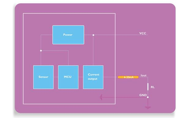
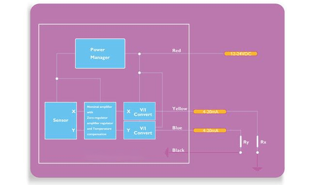
For the inclination sensor with current type output, what is the two-wire system and what is the three-wire system? Look at the following figure, very intuitive, at a glance, Figure 1 is a two-wire system, Figure 2 is a three-wire system. Single-axis two-wire system, two-axis three-wire system, pay attention to the load resistance when in use do not ignore.

Two-wire current output tilt sensorthree-wire current output tilt sensor


What is a digital output tilt sensor?

Digital output is relative to analog, there are many kinds of digital interfaces, such as RS232,TTL, RS485, CAN, PWM, and very rare RS422 interface, SII interface, and other master-slave communication methods. ER-TS-4156DI is a digital single-axis tilt sensor, its output mode has RS232, RS485 or TTL, MODBUS level interface options, it can resist external electromagnetic interference, adapt to harsh industrial environment for long-term work, is an ideal choice for industrial automation control and platform attitude measurement.

Application areas and uses of IMU

Inertial navigation IMU has a wide range of application scenarios and is often used for pointing, steering and guidance monitoring, rock soil monitoring, etc. in advanced mining/drilling equipment, ships, automobiles, drones, robots, oil exploration, bridge exploration, high-rise buildings, iron towers, dams, etc. , navigation and positioning of transportation vehicles such as mining and missiles, and north-finding positioning in geodetic/land mobile mapping systems.


In the automotive field, inertial navigation IMU can help vehicles achieve autonomous driving and traffic jam identification, improving driving performance and safety. In land vehicles, IMUs can be integrated into GPS-based car navigation systems or vehicle tracking systems to provide dead reckoning capabilities to the system and the ability to collect as much accurate data as possible about the vehicle’s current speed, turn rate, heading and inclination and acceleration, combined with the vehicle’s wheel speed sensor output and reverse gear signal for purposes such as better traffic collision analysis. The ER-MG2-300/400 developed by ERICCO is a navigation-grade MEMS gyro sensor with a measurement range of up to 400 degrees/second and a bias instability of 0.05°/hour. It is designed for precision attitude in high-performance IMU/AHRS. Designed for azimuth measurement, positioning, navigation, guidance/GNSS-assisted INS, aviation/marine/land mapping/measurement systems/unmanned aerial vehicle/AUV and navigation-level MEMS weapon systems.

In the aviation field, inertial navigation IMU can realize motion control such as aircraft climbing, descending, turning, taxiing, etc., improving flight safety and accuracy. In a navigation system, data reported by the IMU is fed into a processor to calculate altitude, speed, and position. ER-MIMU-01 developed by ERICCO uses high-quality and reliable MEMS accelerometer and gyroscope. It communicates with the outside through RS422. The baud rate can be flexibly set between 9600~921600. The communication baud rate required by the user can be set through the communication protocol. Equipped with X, Y, Z three-axis precision gyroscope, X, Y, Z three-axis accelerometer, with high resolution, it can output the original hexadecimal complement of X, Y, Z three-axis gyroscope and accelerometer through RS422 code data (including gyroscope hexadecimal complement) numerical temperature, angle, accelerometer hexadecimal temperature, acceleration hexadecimal complement); it can also output gyroscope and accelerometer data that have been processed by underlying calculations Floating point dimensionless value.

One of the earliest devices was designed and built by the Ford Instrument Company for the U.S. Air Force and was intended to help aircraft navigate in flight without requiring any input from outside the aircraft. The device, known as a ground position indicator, shows the pilot the aircraft’s longitude and latitude relative to the ground once the pilot inputs the aircraft’s longitude and latitude during takeoff.

A major disadvantage of using IMUs for navigation, then, is that they are often subject to cumulative errors. Because the guidance system continuously integrates acceleration versus time to calculate velocity and position (see dead reckoning), any measurement error, no matter how small, accumulates over time. This results in “drift”: an increasing discrepancy between where the system thinks it is and where it actually is. The ER-MG-067 developed by ERICCO is a high-precision tactical-grade MEMS gyroscope with an instability deviation of 0.3 degrees/hour and an angular random walk of 0.125°/√h. It is a single-axis MEMS angular rate sensor. (gyroscope), capable of measuring angular velocity up to ±400°/s, and the digital output complies with the SPI slave mode 3 protocol. Angular rate data is represented as 24-bit words.

If you want to know more about imu's products, please click the link below to contact us, and we will have professional personnel connect with you.

Web:https://www.ericcointernational.com/inertial-measurement-units

Email: info@ericcointernational.com

Whatsapp: 13630231561

WeChat13992884879


Choose a suitable IMU to make your drone flight more stable and safe

         As one of the core components of drones, IMU plays an irreplaceable role. Its high precision, fast response and freedom from extern...