Tuesday, May 7, 2024

Methods to Improve the Orienting Efficiency of Gyro Theodolite

https://www.ericcointernational.com/application/methods-to-improve-the-orienting-efficiency-of-gyro-theodolite.html

Ultra High Accuracy Gyro Theodolite

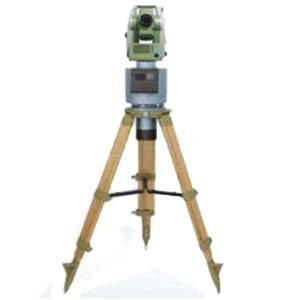
The gyro theodolite is a measuring instrument used to determine the true north azimuth angle. It mainly consists of a gyroscope and a theodolite. The gyroscope uses its own physical properties, such as axiality and precession, to be sensitive to the horizontal component of the earth's rotation angular velocity, thereby determining the true north azimuth angle. This instrument is widely used in fields such as mine surveying, engineering surveying, and military surveying and mapping. It is also an important supporting equipment for radar antenna orientation, UAV flight orientation, artillery and remote weapon launch orientation. Next we will propose some methods to improve the directional efficiency of gyro theodolite.


1.Factors affecting the directional efficiency of gyro theodolite

1) It takes a long time to measure the instrument constants before and after orientation, which is even more troublesome when the weather is bad. According to the requirements of the regulations, it is necessary to compare with the known sides twice before and after orientation to determine the instrument constants. Normally, two walking and directional measurements take half a day.

2) Directional measurement requires multiple measurement rounds. For example, using a 15~20s instrument requires 4 measurement rounds. The purpose is to improve accuracy and avoid errors, which usually takes 2h.

3) The final directional measurement results cannot be obtained at this time. Because the final orientation result cannot be obtained until a series of in-house calculations such as post-measurement constants, meridian convergence angles, and coordinate azimuth angles are completed, it takes two visits to the site to complete the subsequent measurement work of the orientation, such as accurately specifying the orientation. .

4) Some gyro theodolite or automatic gyro theodolite require a long waiting time. Some instruments need to pre-suspend the gyroscope in order to obtain more stable readings and reduce rework. This time is from tens of minutes to 1 hour;

5) When the instrument comes from the cold ground to the well, it will fog up and it will take 0.5 hours for the water vapor to dry.

6) Windproof treatment at the directional measurement site or organize and coordinate the shutdown of other work on site. This is because manual gyro theodolite cannot work in wind and vibration environments. This is because the manual gyro theodolite cannot work in an environment with wind and vibration. The nutation of the gyro indicator line often causes orientation errors to exceed limits and rework. It takes more time to coordinate and solve this problem.

7) Gyro-theodolite or high-precision automatic gyro theodolite can only solve the orientation problem. Actual surveying work often requires the completion of other measurements such as positioning, orientation, and stakeout at the same time. Usually, other instruments and personnel are required, and even need to be carried out again. In this way, the total man-time consumption is even more.

It can be seen that under normal circumstances without rework, one orientation takes about 5 to 8 hours. What takes more time is constant measurement, waiting before testing, multiple test orientations, etc. To improve efficiency, these problems should mainly be solved.


2.Methods to improve the orientation efficiency of gyro theodolite

There are many ways to improve the directional efficiency of a gyro theodolite. Here are some suggestions:


  1. Automation and intelligence: With the development of technology, realizing the automation and intelligence of gyro theodolite is the key to improving the orientation efficiency. By introducing automated control systems and artificial intelligence technology, manual intervention can be reduced and measurement accuracy and efficiency improved.
  2. Optimize data processing algorithms: Improve data processing algorithms, reduce data processing time and errors, and improve orientation efficiency. For example, introduce efficient filtering algorithms, optimize data fitting methods, etc.
  3. Strengthen instrument maintenance and calibration: Regularly maintain and calibrate the gyro-theodolite to ensure that the instrument is in good working condition. This can reduce instrument errors and improve measurement accuracy and efficiency.
  4. Improve the skill level of operators: Provide training and assessment to operators to improve their operating skills and familiarity with the instrument. This can reduce operating errors and improve orientation efficiency.
  5. Optimize the observation plan: Choose an appropriate observation plan based on the actual situation, such as selecting the appropriate observation time, optimizing the observation location, etc. This can improve the accuracy and efficiency of observations.
  6. Utilize modern communication technology: The introduction of modern communication technology, such as remote data transmission, real-time data processing, etc., can reduce data transmission and processing time and improve orientation efficiency.
  7. Integrated multi-sensor technology: Integrating the gyro theodolite with other sensors (such as GPS, accelerometer, etc.) can further improve orientation accuracy and efficiency.
  8. Develop new gyro theodolite: Continuously develop new gyro theodolite to improve its measurement accuracy, stability and automation, thereby further improving orientation efficiency.


Summarize

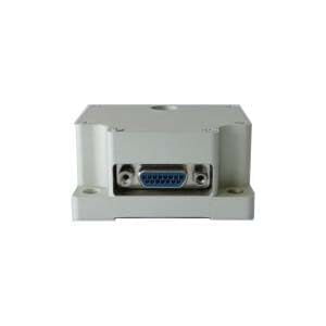
Improving the orientation efficiency of gyro theodolite can be achieved through automation and intelligence, as well as optimizing data processing methods. The gyro theodolite developed by our company not only uses the above-mentioned technology to improve its directional accuracy in the directional navigation function, but more importantly, our company's gyro theodolite has higher directional accuracy. For example, ER-GT-02 is ultra-high precision. Gyro theodolite has the following features:


  1. Orientation accuracy ≤3.6" (1σ);
  2. Strong pit interference capability, integrated body design, compact structure and stable performance;
  3. It has the functions of low position locking, automatic zero adjustment and observation, etc.

If you want to know more product knowledge about gyro theodolite, please contact our professional technical staff.

Precision Analysis of Fiber Optic Gyro Engineering Structure Deformation Detection


1 Method of engineering structure deformation detection based on fiber optic gyroscope

The principle of the engineering structure deformation detection method based on fiber optic gyro is to fix the fiber optic gyro to the detection device, measure the angular velocity of the detection system when running on the measured surface of the engineering structure, measure the operating distance of the detection device, and calculate the operating trajectory of the detection device to realize the detection of engineering structure deformation. This method is referred to as the trajectory method in this paper. This method can be described as "two-dimensional plane navigation", that is, the position of the carrier is solved in the plumb surface of the measured structure surface, and the trajectory of the carrier along the measured structure surface is finally obtained.

According to the principle of trajectory method, its main error sources include reference error, distance measurement error and Angle measurement error. The reference error refers to the measurement error of the initial inclination Angle θ0, the distance measurement error refers to the measurement error of ΔLi, and the Angle measurement error refers to the measurement error of Δθi, which is mainly caused by the measurement error of the angular velocity of the fiber optic gyroscope. This paper does not consider the influence of reference error and distance measurement error on the deformation detection error, only the deformation detection error caused by the fiber optic gyroscope error is analyzed.

2 Analysis of deformation detection accuracy based on fiber optic gyroscope

2.1 Error modeling of fiber optic gyroscope in deformation detection applications

Fiber optic gyro is a sensor for measuring angular velocity based on Sagnac effect. After the light emitted by the light source passes through the Y-waveguide, two beams of light rotating in opposite directions in the fiber ring are formed. When the carrier rotates relative to the inertial space, there is an optical path difference between the two beams of light, and the optical interference signal related to the rotational angular speed can be detected at the detector end, so as to measure the diagonal speed.
The mathematical expression of the fiber optic gyro output signal is: F=Kw+B0+V. Where F is the gyro output, K is the scale factor, and ω is the gyro
The angular velocity input on the sensitive axis, B0 is the gyroscopic zero bias, υ is the integrated error term, including white noise and slowly varying components caused by various noises with long correlation time, υ can also be regarded as the error of zero bias.
The sources of measurement error of fiber optic gyroscope include scale factor error and zero deviation error. At present, the scale factor error of the fiber optic gyroscope applied in engineering is 10-5~10-6. In the application of deformation detection, the angular velocity input is small, and the measurement error caused by the scale factor error is much smaller than that caused by the zero deviation error, which can be ignored. The DC component of the zero-bias error is characterized by the zero-bias repeatability Br, which is the standard deviation of the zero-bias value in multiple tests. The AC component is characterized by zero bias stability Bs, which is the standard deviation of the gyroscope output value from its mean in one test, and its value is related to the sampling time of the gyroscope.

2.2 Calculation of deformation error based on fiber optic gyroscope

Taking the simple supported beam model as an example, the error of deformation detection is calculated, and the theoretical model of structural deformation is established. On this basis, the detection is set
Based on the operating speed and sampling time of the system, the theoretical angular velocity of the fiber optic gyro can be obtained. Then the angular velocity measurement error of the fiber optic gyro can be simulated according to the zero deviation error model of the fiber optic gyro established above.

2.3 Example simulation calculation

The simulation setting of running speed and sampling time adopts a range-varying mode, that is, the ΔLi passed by each sampling time is fixed, and the sampling time of the same line segment is changed by changing the running speed. For example, when the ΔLi is 1 mm, such as the running speed is 2 m/s, the sampling time is 0.5 ms. If the operating speed is 0.1 m/s, the sampling time is 10 ms.

3 Relationship between fiber optic gyroscope performance and deformation measurement error

Firstly, the effect of zero-bias repeatability error is analyzed. When there is no zero bias stability error, the angular velocity measurement error caused by zero bias error is fixed, such as the faster the motion speed, the shorter the total measurement time, the smaller the impact of zero bias error, the smaller the deformation measurement error. When the running speed is fast, the zero bias stability error is the main factor causing the system measurement error. When the running speed is low, the zero bias repeatability error becomes the main source of the system measurement error.
Using typical medium precision fiber optic gyro index, that is, zero bias stability is 0.5 °/h when sampling time is 1 s, Zero repeatability is 0.05 °/h. Compare the system measurement errors at the operating speed of 2 m/s, 1 m/s, 0.2 m/s, 0.1 m/s, 0.02 m/s, 0.01 m/s, 0.002 m/s and 0.001 m/s. When the operating speed is 2 m/s, The measurement error is 8.514μm (RMS), when the measurement speed is reduced to 0.2m /s, the measurement error is 34.089μm (RMS), when the measurement speed is reduced to 0.002m /s, the measurement error is 2246.222μm (RMS), as can be seen from the comparison results. The faster the running speed, the smaller the measuring error. Considering the convenience of engineering operation, the running speed of 2 m/s can achieve better than 10 μm measurement accuracy.

4 Summary

Based on the simulation analysis of the engineering structure deformation measurement based on fiber optic gyro, the error model of fiber optic gyro is established, and the relationship between the deformation measurement error and the performance of fiber optic gyro is obtained by using the simple supported beam model as an example. The simulation results show that the faster the system runs, that is, the shorter the sampling time of the fiber optic gyroscope, the higher the deformation measurement accuracy of the system when the sampling number is unchanged and the distance detection accuracy is guaranteed. With the typical medium precision fiber optic gyro index and the running speed of 2 m/s, the deformation measurement accuracy of better than 10 μm can be achieved.
Ericco's ER-FOG-851 has a diameter of 78.5mm and an accuracy of ≤0.05 ~ 0.1º/h. ER-FOG-910 precision 0.02º/h, belongs to the high tactical level of the fiber optic gyroscope, our company produced gyroscope with small size, light weight, low power consumption, fast start, simple operation, easy to use and other characteristics, widely used in INS, IMU, positioning system, north finding system, platform stability and other fields. If you are interested in our fiber optic gyro, please feel free to contact us.

Monday, April 29, 2024

Analysis of Main Performance Parameters of Fiber Optic Gyroscope


1.Fiber Optic Gyroscope

When measuring the rotation and direction of aircraft and other moving objects, the accuracy of fiber optic gyroscopes is inherently limited by using ordinary classical optical methods.
The phase difference measurement accuracy of fiber optic gyroscope determines the overall precision of rotation measurement. The accuracy of fiber optic gyro is limited by many noise sources, and the main influence factor is shot noise. The quantization of photons produces shot noise. When a single photon passes through a device, its discrete nature means that the flow is not perfectly smooth, resulting in white noise. While it is possible to reduce shot noise by increasing the power (the rate at which photons pass through), the greater the power, the greater the other noise, so there is a trade-off.
At present, due to the low power of the detectors used, the new fiber optic gyroscopes do not yet pose a threat to commercial (classical) fiber optic gyros. The researchers expect that as detector technology advances and photon source brightness increases, entangled photon fiber gyroscopes will be commercially available in the near future. Overall, physicists hope that the current results represent a first step toward pushing the ultimate limits of sensitivity in fiber-optic gyroscopes.
The realization of the fiber optic gyroscope is mainly based on the theory of Segnick: when the light beam travels in a circular channel, if the circular channel itself has a rotational speed, then the time required for the light to travel along the direction of rotation of the channel is more than the time required to travel along the opposite direction of the channel.

2. Main performance parameters of fiber optic gyroscope

Through the above introduction, we must have a preliminary understanding of the fiber optic gyro. In this part, we mainly understand some of the main performance parameters of fiber optic gyroscopes.

2.1 Zero bias and zero drift

Zero bias is the output of the gyroscope when the input angular velocity is zero (i.e. the gyroscope is at rest), expressed as the equivalent input angular velocity corresponding to the average output value measured within a specified time, ideally the component of the Earth's rotation angular velocity. Zero drift is zero bias stability, indicating the degree of dispersion of the gyroscope output around its zero bias mean when the input angular rate is zero, expressed by the equivalent input angular rate corresponding to the standard deviation of the output in a specified time. Zero drift is the most important and basic index to measure the accuracy of FOG(fiber optic gyro). The main factor of zero drift is the non-reciprocal phase shift error introduced in the fiber coil by the ambient temperature variation. In order to stabilize zero drift, temperature control or temperature compensation of IFOG is often required. In addition, polarization will also have a certain influence on zero drift. In IFOG, polarization filtering and polarization-maintaining fiber are often used to eliminate the influence of polarization on zero drift.

2.2 Scale factor

Scale factor is the ratio of the output of the gyroscope to the input angular rate, which can be expressed by a specific linear slope on the coordinate axis. It is an index reflecting the sensitivity of the gyroscope, and its stability and accuracy are an important index of the gyroscope, comprehensively reflecting the test and fitting accuracy of the fiber optic gyro. The stability of the scale factor is dimensionless and is usually expressed in parts per million (ppm). The error of the scale factor mainly comes from the temperature change and the instability of the polarization state of the fiber.

2.3 Random walk coefficient

A technical index to characterize the white noise of the angular velocity output in a fiber optic gyro, it reflects the uncertainty of the angular velocity integral of the fiber optic gyro output over time, so it can also be called an angular random walk. The random walk coefficient reflects the development level of the gyroscope, and also reflects the minimum detectable angular rate of the gyroscope. The error is mainly due to random spontaneous emission of photons, noise and mechanical jitter introduced by photodetector and digital circuit.

2.4 Threshold and resolution

The threshold indicates the minimum input rate that a fiber optic gyro can sense. Resolution represents the minimum input rate increment that a gyroscope can sense at a specified input angular rate. Both threshold and resolution characterize the sensitivity of a fiber optic gyroscope.

2.5 Maximum input angular speed

Represents the maximum input rate of the gyroscope in the positive and negative directions, and represents the dynamic range of the gyroscope, that is, the rate range of the fiber optic gyro can be induced.

3.Summary

When choosing a fiber optic gyros, we mainly look at its zero bias stability, zero bias repeatability, measurement range, etc., such as our Ericco fiber optic gyro ER-FOG-50, its measurement range is -500~500, zero bias stability is 0.2~2.0º/h, zero bias repeatability and zero bias stability are consistent. ER-FOG-60, its measuring range is -1000~+1000, zero bias stability is 0.06~0.5º/h, compared with the ER-FOG-60 measurement range is large, the accuracy is relatively high, of course, we have a variety of medium precision fiber optic gyro models, mainly according to your application scenario to decide. If you are interested in our fiber optic gyro, please feel free to contact us.


Application of Gyro Theodolite in Precision Measurement of large-scale Aerospace Products


For precision measurement of spacecraft equipment installation, a theodolite is usually used to measure the reference cubic mirror on the equipment (hereinafter referred to as the "reference mirror").


To establish a coordinate system through alignment, the fixed-position theodolite is used to aim at each other with multiple other theodolites to achieve datum transfer, and finally the installation attitude relationship between the two devices is obtained. In the complete docking state of the "Tiangong-1" large spacecraft, it is necessary to accurately measure the installation posture of the equipment when replacing equipment in the final assembly platforms at different heights and levels of 9 to 11 m. In order to ensure the accuracy of measurement, the platform must be used to separate humans and machines. This results in the theodolite being unable to aim at each other between different platforms during the measurement process to complete attitude measurement between devices. In order to solve this kind of problem, this paper conducts research on the measurement principle of gyro-theodolite, and cleverly uses the geodetic coordinate system as the intermediate transfer coordinate system to solve the problem of conventional theodolite testing being unable to establish the relationship between the reference mirror coordinate systems due to mutual sighting being blocked.


1.Application of gyro theodolite

1.1 Measuring principle of gyro-theodolite

The gyro-theodolite is an autonomous directional measuring instrument, which is an organic combination of a gyroscope and a theodolite. It uses the fixed axis and precession of the gyroscope to be sensitive to the Earth's rotation, thereby measuring the normal direction of the Earth's rotation, commonly known as the true north direction. It does not require any external information and can measure the true north direction within a range of 75° north and south, thereby obtaining the required orientation. The geodetic coordinate system can be defined by the true north direction and the geodetic horizontal plane. The relationship between the geodetic coordinate system and the theodolite absolute coordinate system is determined based on the reading of the code disk in the horizontal rotation plane of the theodolite in the true north direction.


1.2 Measurement algorithm of gyro-theodolite

The joint construction of the gyro-theodolite and theodolite is a new method. Its principle is to find the north through the gyro-theodolite and determine the true north datum. Use a theodolite to measure the normal pitch angle of the two mutually perpendicular horizontal reflection end surfaces of the measured reference mirror and the azimuth angle of the normal horizontal projection line. Using the relationship between spherical and solid trigonometric functions, the angles between the normals of each end surface of the reference mirror and the three coordinate axes of the geodetic coordinate system are calculated.


After measuring the attitude of the reference mirrors in the same coordinate system, the attitude between any two reference mirrors can be obtained through calculation, which is the attitude relationship between the reference mirrors.


The specific algorithm is as follows: use theodolite and gyro-theodolite to collimate and measure two arbitrarily placed reference mirrors, and perform mutual aiming between instruments after collimation. As shown in Figure 1, assume that the gyro-theodolite has observational quantities T1 (horizontal angle), V1 (elevation angle), a1 (azimuth angle) for the collimation of the cubic mirror, and the theodolite has the observational quantities T4, V2 and longitude for the collimation of the reference mirror. The transferred azimuth angle a2, the mutual aiming measurements of the gyro-theodolite and theodolite are T2 and T3

Figure 1 Reference mirror azimuth transfer diagram


The azimuth angle of the theodolite collimation after mutual aiming transfer can be obtained by the following formula

Based on the azimuth angle and vertical angle of the collimation line on each surface of the reference mirror, the direction cosine of each collimation direction is obtained:

1.3 Analysis of the accuracy error of the north position of the reference mirror measured by the gyro-theodolite

This mainly includes two items: one is the comprehensive error of the north-seeking orientation of the gyro; the other is the error of the theodolite, that is, the theodolite mutual aiming error, theodolite collimation error, and the gyro-theodolite collimation error. The attitude calibration process between cubic mirrors is equivalent to the alignment and mutual aiming measurement of two single reference mirrors. Each mutual aiming and collimation is regarded as the sighting of the theodolite, and the mutual aiming transfers the azimuth angle obtained by the reference mirror.


Summarize

According to the measurement principle of the gyro theodolite, the geodetic coordinate system is used as the intermediate transfer coordinate system, which solves the problem that the theodolite cannot establish the reference mirror coordinate system because the mutual sighting is blocked. The gyro-theodolite developed by ERICCO, such as: ER-GT-02, is a super High-precision gyro theodolite, orientation accuracy ≤3.6" (1σ); has strong pit interference capability, integrated body design, compact structure, and stable performance; most importantly, it can serve large spacecrafts and can be compared For accurate measurements, Ericco also has multiple gyroscopic theodolites.

If you would like to know more, please contact us.

Sunday, April 28, 2024

Ripple Free Minimum Beat Control of Closed-loop FOG Gyro

 The interferometric FOG gyro is a kind of angular velocity sensor based on Sagnac effect, which has the advantages of all-solid state, shock resistance, low cost, small size, etc., and has been widely used in aerospace, aviation, navigation, oil exploration well and other fields. Digital closed-loop IFOG carries out phase modulation according to the feedback signal, eliminates the phase shift caused by the speed, improves the dynamic range and scale factor linearity of IFOG, and is currently the mainstream scheme of medium-high precision IFOG. In the digital closed-loop fiber optic gyroscope, it is necessary to control according to the intrinsic frequency. The intrinsic frequency of different fiber optic gyroscopes is different, and the intrinsic frequency is usually generated by phase-locked loop technology. However, the system clock will have random fluctuations, and the frequency generated by the PLL will also fluctuate, which will lead to ripple interference in the output of the control system, and seriously affect the precision of the digital closed-loop fiber optic gyro.

In order to improve the reliability and adaptability of digital closed-loop IFOG, we established a theoretical model of digital closed-loop IFOG based on the principle of four-state square wave modulation and demodulation, analyzed the stable operating conditions and dynamic performance of digital closed-loop IFOG, and pointed out the shortcomings of the original IFOG digital closed-loop FOG gyro control system. An optimal control scheme of minimum beat without ripple is proposed. The performance of the digital closed-loop FOG gyro before and after optimization is compared by experiments. The results show that the zero bias stability and other performance indexes of the gyroscope after optimization are obviously improved.

1 Theoretical model

The digital closed-loop IFOG structure mainly includes light source, coupler, phase modulator (y-waveguide), optical fiber ring, photodetector, preamplifier, analog/digital converter (ADC), digital logic processor, digital/analog converter (DAC) and output buffer amplifier. The Sagnac interferometer consists of a light source, a coupler, a phase modulator and a fiber ring. When the fiber ring rotates, the phase difference generated by the two light waves traveling opposite each other in the loop is proportional to the rotation rate Ω.

2 Performance analysis and optimization

2.1 Control system performance analysis

The digital closed-loop IFOG frequency bandwidth increases with the increase of open-loop gain K, when the open-loop gain is greater than 0.2, in the high band, the gain is greater than 1. In order to obtain large bandwidth and stable control, 0.2 open loop gain is the best open loop gain.

2.2 Optimization of closed-loop control system

The performance analysis of the IFOG control system shows that the control system is a type I system with steady-state error under the input of angular acceleration. The sampler introduced in the design of integrator and step wave increases the overshoot and decreases the stability of the system. In order to improve the stability of the digital closed-loop FOG gyro, two samplers can be eliminated by output from the front stage of the cache during integral control and step wave generation. According to the control design method of second-order ripple free minimum beat system, the original IFOG controller is modified to eliminate the static error under the ramp input, and the optimized digital closed-loop IFOG ripple free minimum beat control system is obtained.

3. Experiment and result analysis

According to the block diagram of the digital closed-loop IFOG non-ripple minimum beat control system, the input-output relationship of the controller can be obtained as
Y (k) = y (k - 1) + [y (k - 1) - (k - 2)] y + x (k - 1) + [x (k - 1) - x (k - 2)], type: x (k) for k times the amount of error; y(k) is the output at time k. The above analysis shows that the output error and output can be delayed by two control cycles respectively through registers in FPGA, and the change of error and output can be obtained by subtracter and used for integral control, so as to realize the control of ripple free minimum beat system in FPGA.

According to the GJB2426A-2004 test method of FOG gyro, we evaluate the advantages and disadvantages of the non-ripple minimum beat control method by comparing the difference between the original control and non-ripple minimum beat control in the main indexes of FOG gyro, such as zero bias stability, Angle random walk and scale factor nonlinearity. The specific steps are as follows: the original control method and the non-ripple minimum beat control method are used to test the performance index of type 70 fiber optic gyro at room temperature respectively for 1 h. During the experiment, the length of the fiber ring in the fiber optic gyro is 800 m, the average diameter of the fiber ring is 70 mm, and the light source is the superradiation light-emitting diode. The optical wavelength is 1 310 nm, the ADC bit width is 12 bit, and the DAC bit width is 16 bit. The test results show that the output noise of the fiber optic gyro is obviously reduced under the control of the minimum beat without ripple, which indicates that the original control system results in a large output noise due to the influence of the control ripple. The analysis results show that the performance of fiber optic gyro is obviously improved under the control of non-ripple and minimum beat.

4 Summary

The theoretical model of IFOG digital closed loop under four-state square wave modulation is analyzed theoretically. It is pointed out that the original control system is a type I system, and the two-stage delay generated in the process of integral control and step wave generation reduces the reliability of the system, and the steady state error is proportional to the acceleration and inversely proportional to the open-loop control gain under the input of angular acceleration. In order to eliminate the influence of steady-state error, a digital closed-loop FOG gyro control system without ripple minimum beat is designed to eliminate the ripple error caused by the frequency of digital closed-loop IFOG in principle. The experimental results show that the ripple free minimum beat control can effectively improve the performance of digital closed-loop IFOG.

Ericco's ER-FOG-851ER-FOG-910 stable performance, low power consumption, long life, is a very good choice, if you want to buy our fiber optic gyroscope, please feel free to contact us.


Thursday, April 25, 2024

Research on the Drift Pattern of Instrument Constants of Gyro Theodolite with Temperature


Ultra High Accuracy Gyro Theodolite

The law of instrument constant drift with temperature of a gyro theodolite is a complex phenomenon, which involves the interaction of multiple components and systems within the instrument. Instrument constant refers to the measurement reference value of the gyro-theodolite under specific conditions. It is crucial to ensure measurement accuracy and stability.


Temperature changes will cause the drift of instrument constants, mainly because the differences in thermal expansion coefficients of materials cause changes in the instrument structure, and the performance of electronic components changes with temperature changes. This drift pattern is often nonlinear because different materials and components respond differently to temperature.


In order to study the drift of the instrument constants of a gyro theodolite with temperature, a series of experiments and data analysis are usually required. This includes calibrating and measuring the instrument at different temperatures, recording changes in instrument constants, and analyzing the relationship between temperature and instrument constants.


Through the analysis of experimental data, the trend of instrument constants changing with temperature can be found, and an attempt can be made to establish a mathematical model to describe this relationship. Such models can be based on linear regression, polynomial fitting, or other statistical methods and are used to predict and compensate for drift in instrument constants at different temperatures.


Understanding the drift of the instrument constants of a gyro theodolite with temperature is very important to improve measurement accuracy and stability. By taking corresponding compensation measures, such as temperature control, calibration and data processing, the impact of temperature on instrument constants can be reduced, thereby improving the measurement performance of the gyro theodolite.


It should be noted that the specific drift rules and compensation methods may vary depending on different gyro theodolite models and application scenarios. Therefore, in practical applications, corresponding measures need to be studied and implemented according to specific situations.


The study of the drift pattern of instrument constants of gyro theodolite with temperature usually involves monitoring and analyzing the performance of the instrument under different temperature conditions.

The purpose of such research is to understand how changes in temperature affect the instrument constants of a gyro theodolite and possibly find a way to compensate or correct for this temperature effect.


Instrumental constants generally refer to the inherent properties of an instrument under specific conditions, such as standard temperature. For gyro theodolite, instrument constants may be related to its measurement accuracy, stability, etc.

When the ambient temperature changes, the material properties, mechanical structure, etc. inside the instrument may change, thus affecting the instrument constants.


To study this drift pattern, the following steps are usually required:

  1. Select a range of different temperature points to cover the operating environments a gyroscopic theodolite may encounter.
  2. Take multiple directional measurements at each temperature point to obtain sufficient data samples.
  3. Analyze the data and observe the trend of instrument constants as a function of temperature.
  4. Try to build a mathematical model to describe this relationship, such as linear regression, polynomial fitting, etc.
  5. Use this model to predict instrument constants at different temperatures and possibly develop methods to compensate for temperature effects.


A mathematical model might look like this:

K(T) = a + b × T + c × T^2 + ...

Among them, K(T) is the instrument constant at temperature T, and a, b, c, etc. are the coefficients to be fitted.


This kind of research is of great significance for improving the performance of gyro theodolite under different environmental conditions.

It should be noted that specific research methods and mathematical models may vary depending on specific instrument models and application scenarios.


Summarize

Overall, by systematically collecting and analyzing data, we can better understand how the instrument constant of a gyroscopic theodolite changes with temperature and take corresponding measures to optimize its performance. The shedding or theodolite developed by ERICCO takes optimization measures when the instrument changes with normal temperature. ER-GT-02 is an ultra-high-precision gyro theodolite with an orientation accuracy of ≤3.6" (1σ); it has strong pit interference capability, integrated body design, compact structure, and stable performance; most importantly, it has low-level locking , automatic zeroing observation and other functions. Similarly, Ericco has multiple gyro theodolite.


If you are interested in learning more about gyro theodolite, please contact us.

Transformation Relationship of IMU Coordinate Axes


Application of High Accuracy North-Seeking MEMS IMU

1. Transformation relationship of IMU coordinate axes

1.1IMU coordinate system

An IMU (Inertial Measurement Unit) is a sensor device that integrates an accelerometer, gyroscope, and magnetometer and is used to measure and calculate the acceleration, angular velocity, and direction of an object.

The IMU coordinate system is a reference coordinate system determined by the IMU sensor and consists of three coordinate axes: x-axis, y-axis, and z-axis.

The IMU coordinate system is usually referenced to three mutually perpendicular axes, and the specific directions vary depending on the device.

2. Definition of coordinate axes

x-axis: parallel to the IMU device and pointing to the front of the device.

y-axis: parallel to the IMU device, pointing to the right side of the device.

z-axis: parallel to the IMU device, pointing toward the top of the device.

3. Coordinate transformation relationship of IMU

There is a certain transformation relationship between the IMU coordinate system and the inertial space coordinate system.

This transformation relationship can be expressed by a rotation matrix, usually denoted as R, which is the rotation relationship between the inertial space coordinate system and the IMU coordinate system.

Assuming that the coordinates of the inertial space coordinate system are P and the coordinates of the IMU coordinate system are P’, the transformation relationship between the two can be expressed as: P’ = R * P.

This transformation relationship is determined by the placement angle of the sensor. Through calibration and precise measurement, an accurate rotation matrix can be obtained.

In addition, since IMU devices usually have errors, calibration and filtering operations are required to improve measurement accuracy and reduce errors.

4.Application

4.1Pose estimation

By monitoring the object's acceleration and angular velocity through the IMU sensor, the object's attitude can be estimated using the transformation relationship of the coordinate axes.

Posture represents the direction and rotation state of an object in three-dimensional space, and is widely used in fields such as robots, drones, and virtual reality.

4.2Sports tracking

The IMU sensor is used to measure the acceleration and angular velocity of an object, and the movement trajectory of the object can be tracked based on the transformation relationship of the coordinate axes.

Motion tracking technology is often used in sports training, posture analysis, sports simulation and other fields, and is crucial for accurately measuring and analyzing the motion status of objects.

4.3Posture control

By measuring the acceleration and angular velocity of the object through the IMU sensor, and combining the transformation relationship of the coordinate axes, the posture control of the object can be achieved.

Posture control is widely used in robots, smart wearable devices, game controllers and other fields to achieve precise motion control and interactive experience.
The transformation relationship of the IMU coordinate axis describes the rotation relationship between the inertial space coordinate system and the IMU coordinate system.

Through precise calibration and measurement, an accurate rotation matrix can be obtained, which is used to transform the coordinate system and implement application scenarios such as attitude estimation, motion tracking, and posture control.

Conclusion

The transformation relationship of the IMU coordinate axes is described by the rotation matrix.
Through calibration and precise measurement, an accurate rotation matrix can be obtained, thereby realizing the conversion relationship between the inertial space coordinate system and the IMU coordinate system. The MEMS IMU independently developed by ERICCO has higher accuracy. For example, ER-MIMU-01 is a navigation level with built-in Gyro bias instability: 0.02 deg/hr, and ER-MIMU-08 is a tactical level with built-in Bias instability ≤1°/h.
In practical applications, understanding the transformation relationship of IMU coordinate axes is of great significance for tasks such as attitude estimation and motion tracking. Welcome to consult.

Choose a suitable IMU to make your drone flight more stable and safe

         As one of the core components of drones, IMU plays an irreplaceable role. Its high precision, fast response and freedom from extern...