Monday, December 26, 2022

High Performance Dynamic FOG North Seeker

 ER-FNS-01 High Performance Dynamic FOG North Seeker (0.02°-0.5°)


Introduction


ER-FNS-01 High Performance Dynamic FOG North Seeker (0.02°-0.5°) consists of high precision, rugged solid FOG, quartz accelerometer, data acquisition and processing unit. It can provide its true north position information when the carrier moves. At the same time, the information of motion attitude, velocity and position of the carrier can also be displayed. This dynamic north seeker is suitable for static and dynamic initial alignment of missile launch, weapon aiming, direction control of radar, antenna and land surveying and mapping.


https://www.ericcointernational.com/north-finders/fiber-optic-gyro-north-finder/dynamic-fiber-optic-gyro-north-finder.html


Applications


North seeker


Navigation and control


Attitude reference system


Guidance


Vehicle and ship attitude measurement


Integrated inertial/satellite navigation system


Drilling and production system


Mobile mapping system


On-the-move

Specifications

Parameters

ER-FNS-01A

ER-FNS-01B

ER-FNS-01C

ER-FNS-01D

Outline dimension (mm)

248×248×180

248×248×180

248×248×180

248×248×180

Weight (kg)

20Kg

18Kg

15Kg

15Kg

Power supply

AC220V, 50Hz/AC110V, 60Hz/DC18V~36V

Power consumption

≤50W

≤50W

≤50W

≤50W

Start time

3min

3min

3min

3min

Latitude

-70°~+70°

-70°~+70°

-70°~+70°

-70°~+70°

North seeking precision

0.02°secψ

0.06°secψ

0.1°secψ

0.5°secψ

North seeking time

5min

5min

3min

3min

Roll pitch accuracy

0.02°

0.06°

0.1°

0.5°

Heading measurement range

-65°~+65°

-65°~+65°

-65°~+65°

-65°~+65°

Roll pitch measurement range

0°~360°

0°~360°

0°~360°

0°~360°

Positional accuracy

0.8nm/h

1.2nm/h

1.5nm/h

2nm/h

Output mode

RS422

RS422

RS422

RS422

Working temperature

-40℃~+60℃

-40℃~+60℃

-40℃~+60℃

-40℃~+60℃

Vibration environment

20Hz~2000Hz, 6.06g

Impact environment

8ms~11ms, 30g

8ms~11ms, 30g

8ms~11ms, 30g

8ms~11ms, 30g


FAQ:


1. What are the quotation methods?


If you have DHL or Fedex account, we can quote EXW price, otherwise CIF or FOB price.


2. Are there any discounts?


After we submit the sample price, if more quantity is needed, we will quote the bulk price.


3. How long will it take to deliver the goods after placing the order?


For sensors, parts and modules: in stock-one week; no stock-2-4 weeks; For systems, generally, 8-12 weeks.


4. How to deal with the quality problems?


After confirming that the product has quality problems, we will replace it for you free of charge in the shortest possible time.


If interested in High Performance Dynamic FOG North Finder, pls contact us: info@ericcointernational.com

Wednesday, April 13, 2022

Application of ER-MG2–100 (0.02°/h) High Precision MEMS Gyroscope


The ER-MG2–100 is a micromachined single-axis gyro sensor. ER-MG2–100 provides highly accurate north-seeking angular rate (gyroscope) measurement with market-leading low power consumption, the bias stability (Allan variance) is only 0.02°/h, and the Bias stability (1σ 10s) is only is 0.1°/h. The ER-MG2–100 is optimized for high accuracy and stability. ER-MG2–100 is designed for north-seeking, advanced differential sensor design rejects the influence of linear acceleration. Angular rate data is presented as a 24-bit word.


Friday, April 1, 2022

Application of Optical Fiber Gyroscope

The fiber optic gyroscope is an instrument that can accurately determine the position of a moving object. It is an inertial navigation instrument widely used in modern aviation, navigation, aerospace, and defense industries. The fiber optic gyroscope is a sensitive element based on the optical fiber coil, and the light emitted by the laser diode propagates along with the optical fiber in two directions. The difference in light propagation path determines the angular displacement of the sensitive element. Compared with traditional mechanical gyroscopes, fiber optic gyroscopes have the advantages of all-solid-state, no rotating parts and friction parts, long life, large dynamic range, instant start, simple structure, small size, and lightweight. Compared with laser gyroscopes, fiber optic gyroscopes do not have the problem of blocking and do not need to precisely process the optical path from the quartz block, and the cost is relatively low.

Double Axis FOG Gyroscope

The realization of the fiber optic gyroscope is mainly based on the Segnik theory: when the beam travels in a circular channel if the circular channel itself has a rotation speed, then the time required for the light to travel along the channel’s rotation direction is longer than that along the channel. It takes more time to rotate in the opposite direction. That is to say, when the optical loop rotates, in different traveling directions, the optical path of the optical loop will change relative to the optical path of the loop when the loop is stationary. Using this change in the optical path to detect the phase difference between the two optical paths or the change in interference fringes, the rotational angular velocity of the optical path can be measured. This is the working principle of the fiber optic gyroscope. “The characteristics of fiber optic gyroscopes: low energy consumption, long lifespan, and strong reliability. It is also the characteristics of fiber optic gyroscopes that determine it has always been dominant in strategic gyroscopes. This is also an important reason why ERICCO has been committed to promoting the development of FOG.” The CEO of ERICCO said.

The application of fiber optic gyroscope is very wide:

1. Navigational applications Compass is important navigation equipment for ships, mainly including the magnetic compass and gyrocompass. With the development of fiber optic gyroscope technology and the improvement of commercialization, fiber optic gyroscopes have become a new member of marine navigation equipment and are used in commercial and military ships and marine equipment. The fiber optic gyroscope compass based on strapdown inertial navigation system has its rotation axis corresponding to the three axes of the ship’s coordinate system. It can not only be used as a high-precision heading information source to realize automatic north finding and pointing, but also can be obtained Reliable data such as the rate of heading rotation, the angle of roll and pitch, and the rate of rotation of the heading further promote the automated development of ships, ensuring the ship’s maneuvering effects and ensuring the safety of navigation.

2. Aerospace and space applications In aerospace and space applications, high-precision interferometric fiber optic gyroscopes are generally used. IFOG is the strapdown inertial navigation system of the main inertial element, which can provide the aircraft with three-dimensional angular velocity, position, angle of attack, and sideslip angle, and realize the tracking and measurement of a rocket launch. It can also be used for space vehicle stabilization, photography/surveying, mapping, attitude measurement control, motion compensation, EO/FLIR stabilization, navigation and flight control, etc. Among them, the high-precision, high-reliability fiber optic gyroscope, and GPS combined attitude determination has become a spacecraft at home and abroad The typical configuration of the posture system. Like ERICCO’s ER-FOG851, is designed with the concept of traditional fiber optic gyroscope and adopts matured fiber optic gyroscope manufacturing technology. It owns characteristics of small volume, lightweight, low power consumption, fast start-up, simple operation and convenient to use, etc.

3. Military applications The fiber optic gyroscope has a wide range of military applications due to its superiority in angular rate and acceleration measurement and its significant advantages in dynamic range, sensitivity, and reliability. It can be used for positioning, orientation, and navigation of tanks, submarines, self-propelled artillery, and armored assault vehicles; when satellite navigation is in strong electronic interference and cannot obtain accurate information, fiber optic gyros can be used to ensure autonomous navigation, precise guidance and accurate hitting of the target. At the same time, the FOG component is also an important part of the aviation fire control system, which can be used to stabilize the sightline and firing line of weapon systems such as armed helicopters, ensuring that the weapon can search, aim, track and shoot in motion. In addition, the fiber optic gyroscope is also the only effective navigation technology underwater, which can be used for positioning, orientation, and navigation of submarines.

4. Civilian applications In the civil field, it mainly focuses on the application of low- and medium-precision fiber optic gyroscopes. The main applications are automatic navigation, positioning and orientation of ground vehicles, vehicle control; attitude control of agricultural aircraft, sowing and spraying pesticides; in underground engineering maintenance, looking for damage Positioning tools and rescue tools for the position of power lines, pipelines and communication optical (electric) cables; used for geodetic surveying, mineral exploration, petroleum exploration, oil drilling steering, tunnel construction, etc. positioning and path survey, and the use of optical fiber gyro rotation angle And linear displacement to achieve dam inclination measurement and so on. Due to its high cost, its use still has great limitations. Beixun has developed cost-effective fiber optic gyroscope products in response to this problem, which has also promoted the rapid development of my country’s high-precision industry.

Ericco is an industry leader with rich product experience in the field of optical fiber gyroscopes. If you want more details about our products, you can log in to https://www.ericcointernational.com/.

FOG North Seeker

MEMS North Seeker

Land Positioning and Orientation System

mining north finder

mining north seeker

MEMS Inertial navigation system

inertial survey system

integrated navigation system

Attitude Heading Reference System (AHRS)

gyro theodolite

digital compass

electronic compass

tilt sensor

inclination sensor

Electronic Compass and Gyroscope


MEMS Gyro

MEMS gyroscopes are not the earliest motion sensors used in consumer electronics. Acceleration sensors and electronic compasses entered the consumer electronics market earlier. Although the acceleration sensor with reference to gravity and the electronic compass with reference to geomagnetism can form vertical and horizontal three-dimensional space coverage on the earth’s surface, because both of them use the earth rather than the object itself as the reference object, they cannot simulate well. the entire motion of an object. In addition, since the accelerometer is easily disturbed by the force generated during linear motion, and the electronic compass is easily disturbed by other magnetic fields such as metals and mobile phones, its application is greatly limited.


The electronic compass mainly detects the geomagnetism. Common electronic compasses are mainly based on the Hall effect. However, the geomagnetic environment is not perfect. For example, the south pole of the geomagnetism does not necessarily point to the same north on different surfaces of the earth; and at different latitudes of the earth, the angle between the direction of the geomagnetism and the horizontal direction is also different. Therefore, the electronic compass can only point to a general direction, and then correct it. In addition, electronic compasses are also susceptible to interference from magnetic fields such as metals, speakers, and antennas.

The gyroscope, a sensor that measures angular velocity, not only uses the object itself as a reference, but also has high precision, so it can be a useful supplement to other motion sensors, thus making motion detection more complete. A gyroscope can be a useful complement to an accelerometer and an electronic compass. When a three-axis gyroscope is combined with a three-axis acceleration sensor to form a six-axis motion sensor, basically all forms of motion can be detected, including parameters such as speed, direction, and displacement.


There are no more than six kinds of motion of an object, displacement in three directions of X, Y, and Z and rotation in three directions of X, Y, and Z. These six motion modes constitute the complete motion trajectory of the object. If an electronic compass is added to the six-axis motion sensor, the absolute position can be corrected while the motion trajectory is detected to achieve perfect object motion trajectory tracking. Therefore, the further development and application of the gyroscope in the future are closely related to the acceleration sensor and the electronic compass. 


Thursday, March 31, 2022

How MEMS ‘accelerate’ North Finder


Wednesday, March 30, 2022

The Development Potential of MEMS Sensors

MEMS technology was first conceived in 1959 by Richard Pfeynman (who won the Nobel Prize in Physics in 1965). In 1962, the silicon miniature pressure sensor came out.​​

In 1979 Roylance and Angell began the development of piezoresistive microaccelerometers. In 1991 Cole began the development of capacitive micro-accelerometers.​​

Inertial sensors include accelerometers (or accelerometers) and angular velocity sensors (gyroscopes) and their single-, dual-, and triple-axis combined IMUs (inertial measurement units), AHRS (attitude reference systems including magnetic sensors).​​


The MEMS accelerometer is a sensor that uses the inertial force measurement of the sensing mass, and is generally composed of a standard mass (sensing element) and a detection circuit. According to different sensing principles, there are mainly piezoresistive, capacitive, piezoelectric, tunnel current, resonance, thermoelectric coupling and electromagnetic.​​

In 1998, the US CSDL designed and developed the earliest MEMS gyroscope. In the same year, the Drapor laboratory developed another form of MEMS gyroscope. The MEMS gyroscope is made by using the principle of the Coriolis effect when the vibrating mass is rotated by the base (shell) to sense the angular velocity. The main form is frame drive Type (both inner and outer frame) comb drive type, electromagnetic drive type, etc.​​

Low-precision MEMS inertial sensors are mainly used in mobile phones, game consoles, music players, wireless mice, digital cameras, PDs, hard disk protectors, smart toys, pedometers, anti-theft systems, GPS navigation and other portable products as consumer electronic products. Due to the basic measurement functions such as acceleration measurement, tilt measurement, vibration measurement and even rotation measurement, consumer electronics applications to be explored will continue to emerge.​​

Intermediate MEMS inertial sensors, as industrial-grade and automotive-grade products, are mainly used in automotive electronic stability systems (ESP or ESC) GPS-assisted navigation systems, automotive airbags, vehicle attitude measurement, precision agriculture, industrial automation, large medical equipment, robots, Instrumentation, construction machinery, etc. For example, ERICCO’s high-precision MEMS inertial sensors, as military-grade and aerospace-grade products, mainly require high accuracy, full temperature range, and shock resistance. It is mainly used for stability applications such as communication satellite wireless, UAV navigation, directional drilling and mining, and optical aiming systems; control applications such as aircraft flight control, attitude control, yaw damping, etc., as well as guidance applications such as automatic driving and inertial GPS navigation, remote Aircraft, ships, instruments, robots, etc.


How MEMS inertial sensors work

MEMS inertial sensors are based on integrated circuit technology and micromachining technology, and are manufactured on single crystal silicon wafers. The working principle of MEMS inertial sensor is Newton’s law in classical mechanics. Its function is to measure the center of mass motion and attitude motion of moving objects (such as vehicles, aircraft, missiles, ships, artificial satellites, etc.), and then can control and navigate moving objects. Compared with non-MEMS inertial devices, the size and price of MEMS inertial devices can be reduced by several orders of magnitude, which is of great strategic significance for national defense and large-scale mining drilling. The construction of low-cost, high-performance miniature inertial navigation systems based on MEMS inertial devices is becoming a research hotspot in the field of inertial technology.

Testing of MEMS Inertial Sensors

The test of the MEMS inertial sensor is different from the general IC test in that it requires external stimulation, so in addition to the common configurations such as automated test equipment (ATE), ATE interface board (DIB) and device nest board (DUT board), it also needs An extremely important device – the device that generates and delivers the stimulus. The device is customized, and different sensors, especially different types of sensors, are used differently, or even completely different. Therefore, such devices are often not standardized in the industry, and customers must develop corresponding devices together with device manufacturers while designing new inertial sensors. The cost of this development is very expensive, in the millions of dollars. Even if the sensor package shape is changed, the test surface or cavity must be redesigned, which typically costs $200,000 and 8 to 12 weeks. Without a factory for agency testing, even if a small company can design and produce inertial sensors, it is difficult to sell in large quantities.​​

In addition, test time is an important factor affecting the cost of products, especially inertial sensors, because mechanical stimulation tends to be much slower than general circuit measurements. Moreover, the mechanical stimulus had to wait enough time after triggering to stabilize, and it also had to wait enough time after switching off to completely disappear. In order to shorten the test time, in addition to improving the mechanical design of the equipment, improving the parallelism of the test is an immediate solution.

Application areas of MEMS sensors

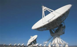
The main application areas of MEMS micro-inertial sensors are automotive, inertial navigation, consumer electronics, mining drilling, drone navigation, and accelerometers and gyroscopes account for a large proportion. At present, although the cost of micro gyroscope is lower, compared with FOG, most MEMS sensors in the market still cannot achieve the same accuracy as FOG, and its application potential has not been fully developed, but if the technology can break through the accuracy between FOG and FOG barriers, then there will be great market potential in the navigation system. For example, ERICCO’s ER-MG2-100 has successfully achieved a technological breakthrough, reaching the same accuracy as FOG, and the deviation instability is only 0.02°/h, making it the leader in MEMS gyroscopes.


Development Trend of MEMS Inertial Sensors

The development trend of MEMS inertial sensors mainly includes the following aspects:

1. Technical aspects: Accuracy will continue to improve. Taking gyroscopes as an example, there is a tendency to replace low-precision fiber optic gyroscopes. For consumer applications, there is a trend to further simplify the manufacturing process and reduce costs. At the same time, integration is also the trend of future development. Not only do module manufacturers take the path of software and hardware integration, but more and more upstream chip manufacturers also take the technical route of integrated blocks. As a result, dual-axis, triple-axis totalizers, and gyro chips have been introduced.​​

2. In terms of competitiveness: the consumer category will have the most fierce competition, and new manufacturers will continue to flood in. It will be an inevitable trend to compare investment and scale. Upstream and downstream rivalry, acquisitions, and reorganizations will be staged.​​

3. Cooperation: due to product segmentation, global competition and cooperation are inevitable results. Upstream manufacturers hope to find downstream customers, and downstream companies hope to find suitable suppliers, so industry alliances may appear.​​

4. Application: No doubt, whether it is a consumer application or industrial-grade military-grade application, the market will expand rapidly and the application will become more and more extensive. If you want to know more product information, please visit to https://www.ericcointernational.com/.

MEMS sensors

MEMS sensors stocks

MEMS based sensors

MEMS sensors mems

MEMS vibration sensors

MEMS inertial sensors


Tuesday, March 29, 2022

Applications of MEMS Sensors

 The full name of MEMS is a micro-electromechanical system, which uses traditional semiconductor technology and materials to integrate micro-sensors, micro-actuators, micro-mechanical mechanisms, signal processing, and control circuits, high-performance electronic integrated devices, interfaces, communications, and power supplies. device or system. It has the characteristics of small size, low cost, and integration.

1. Wearable device application

Taking the Xiaomi Mi Band as an example, MEMS acceleration and heart rate sensors are used to monitor exercise and heart rate. In addition to the MEMS accelerometer, gyroscope, MEMS microphone, and pulse sensor inside the Apple Watch.

2. VR application

VR equipment needs to accurately measure the speed, angle, and distance of head rotation. Using MEMS accelerometers, gyroscopes, and magnetometers to measure is one of the important solutions, and it has almost become the standard configuration of VR equipment.

3. UAV application

In terms of UAV flight attitude control technology, MEMS sensors have room to display. Combining the accelerometer and gyroscope, the angle change can be calculated and the position and flight attitude can be determined. MEMS sensors can work in a variety of harsh conditions while obtaining high-precision output. The application of MEMS accelerometers and gyroscopes on drones can be said to shine. However, several challenges complicate UAV system design, such as motors that are not perfectly calibrated, system dynamics that may vary depending on payload, sudden changes in operating conditions, or errors in sensors. These challenges can lead to biased positioning processing and, ultimately, positional biases during navigation and even failure of the drone. High-quality MEMS sensors and advanced software are essential for industrial drones to go beyond toys. ERICCO has always been committed to the research of high-quality and high-precision MEMS sensors, ERICCO believes the product always wins with performance. ER-MG2–300/400 gyroscopes are often used for drone navigation and are well received.

4. Autonomous driving applications

The rise of autonomous driving technology has further propelled MEMS sensors into cars. Although the GPS receiver can calculate its own position and speed, in places with poor GPS signal (underground garages, tunnels) and when the signal interferes, the car’s navigation will be affected, which is a fatal flaw for autonomous driving. Using MEMS gyroscopes and accelerometers to obtain speed and position (angular velocity and angular position), any subtle movements and tilt attitudes of the vehicle are converted into digital signals and transmitted to the onboard computer through the bus. Even at the fastest vehicle speeds, the precision and response speed of MEMS can adapt. Thanks to the development of silicon micromachining, wafer bonding and other technologies, the accuracy of ERICCO’s ER-MG2–100 gyroscope has reached 0.02°/h, and the ER-MG2–100 even performs better in the test data feedback from customers. If you want to know more product information, please visit our website: https://www.ericcointernational.com/.

Choose a suitable IMU to make your drone flight more stable and safe

         As one of the core components of drones, IMU plays an irreplaceable role. Its high precision, fast response and freedom from extern...