Tuesday, April 9, 2024

Analysis of strapdown north finder data acquisition technology

 With the development of inertial technology, strap-down north finder has become the main trend of development because of its speed, high reliability, no need to provide geographical location information and simple structure. North finder plays an important role in military applications such as missile launching and artillery aiming. In practical engineering applications, the operating latitude of the north finder is from 53° South to 53° north. In the range of Earth latitude 0° ~ 53°, the north component of the earth's rotation angular velocity varies greatly, and the amplitude of the gyroscope output signal will have a large difference. When the sampling resistance of the signal acquisition system is fixed, the gyro data fitting curves are different in different geographical latitudes, and some geographical latitude data fitting curves will lead to data loss, which will have a certain impact on north finding.


1.The overall design of strap-downnorth finding system


The strap-down north seeking system is composed of data acquisition and processing system, turntable leveling system (inclinometer), rotation control system (servo unit), inertial measurement system (fiber optic gyro and accelerometer), temperature control system (temperature control unit), etc. The data acquisition and processing system is composed of signal acquisition module, signal processing module, data display module and data communication module, which is the central processing core of the north finder, mainly realizing the function of data acquisition and processing and calculating the north seeking angle. The signal acquisition module converts the current signal output by the gyro into voltage signal, and then converts it into digital signal through A/D. The signal processing module performs digital filtering on the gyro data, processes the gyro data and encoder data of multiple transposition positions, and calculates the north seeking angle. The data display module displays the working state and north seeking angle data of the north finder; Data communication module communicates with servo control unit, temperature control unit, electronic inclinometer, encoder and host computer through serial port, and sends and receives data.


2.Fiber optic gyroscope data acquisition


The fiber optic gyro adopts differential pulse output mode. The output of each gyro consists of positive and negative pulses. The pulse frequency varies with the carrier's angular velocity. The range is 0~2MHZ and the pulse width is 250ns. How to ensure that the pulse is not lost is very important, so the design of high frequency and reliable pulse counting to count the output pulse of the gyroscope, in order to prevent the interference of the peak jitter pulse, the gyro pulse is firstly filtered and shaped in the front end of the pulse counter module, and then the level frequency doubling sampling is adopted, because the sampling triggered by the pulse rising edge or falling edge will produce false triggering, and the reliability is low.


The update frequency of IMU data in the north finder is 100 Hz, that is, the gyroscope data sampling period is 10ms. When the 10ms interrupt signal rises, the positive and negative counters will be subtraction to obtain the gyroscope data. The result will be temporarily stored in the register, and the counter will be cleared to zero to start the next count. The gyro data in the register is sent to the data RAM for DSP reading when the 10ms interrupt signal falls along the edge. In addition, in order to improve sampling accuracy of the system, oversampling technology is adopted during sampling, that is, a large number of gyro data are collected within each sampling period, and then used for azimuth solution after smoothing and filtering.


In order to verify the correctness and reliability of the design of the pulse counter, a signal generator is used to generate pulse signals, which are connected to the pulse acquisition port of the data acquisition unit, the number of pulses generated by the signal generator is collected in a fixed period of time, and sent to the computer through the serial port. The experimental results are shown in Table 1, where the pulse width is 80ns, the amplitude is 3.3V, and the sampling time is 10ms.
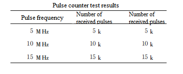
It can be seen from the measurement diagram that the number of pulses sent by the signal generator and the number of pulses collected 1 verify the correctness of the design of the pulse counter. The output of the accelerometer is converted into A pulse signal after A/D conversion, which is similar to the gyroscope data acquisition, and will not be repeated.


3.Serial port expansion


The IMU and attitude data need to be sent to the upper control microcomputer through the serial port. The DSP chip in this system has only one synchronous serial port, so it is necessary to design an asynchronous serial port. For the extension of DSP synchronous to asynchronous serial port, the traditional method is to use special asynchronous communication devices to achieve. Based on the abundant I/O resources of FPGA, this paper uses Verilog language to describe UART and realize the conversion of synchronous and asynchronous protocols, which not only simplifies the hardware circuit but also reduces the burden of DSP. At the same time, using FPGA to design the serial port can reduce the cost and volume of the system and has the advantages of easy transplantation and upgrading.


Conclusion


From the perspective of practical application, this paper introduces the system design in detail, aiming at the requirement of real-time, reliability and precision, multi-channel data acquisition unit of north seeker. Based on the data acquisition technology of north seeker, Ericco continues to improve its own technology, if you are interested, welcome to check our specific products, among which ER-FNS-03 solves the expensive characteristics of traditional FOG north finder with the advantage of low cost, ER-MNS-05 and ER-MNS-06 combine with MEMS technology, manufacture a small medium and high precision north finder, welcome to your understanding.


The full article can be seen: https://www.ericcointernational.com/application/analysis-of-strapdown-north-finder-data-acquisition-technology.html
Application of Gyroscope Theodolite in Measurement of Long Underground Wires

https://www.ericcointernational.com/application/application-of-gyroscope-theodolite-in-measurement-of-long-underground-wires.html

The gyro-theodolite is an instrument that combines a gyroscope and a theodolite. Because it is not limited by time and environment, and its observation is simple, convenient and efficient, it can ensure high orientation accuracy (the error of one orientation is between 5" and 2' ), that is, except for high latitude (usually above 75°) areas on the earth, the true meridian position of any point on the ground or underground and the geodetic azimuth angle of any survey line can be measured, and the orientation accuracy is not affected by altitude. In addition to being used for detection In addition to core and alternative geometric orientation, the direction-attached conductor can also be formed by appropriately adding gyro directional edges on long branch conductors to improve conductor point accuracy.

Characteristics and principles of gyro-theodolite

1.Characteristics of gyroscopic theodolite

The gyro-theodolite is a high-precision measuring instrument that is widely used in geodetic surveying, engineering surveying, aerial photogrammetry and other fields. Its characteristics are mainly reflected in the following aspects:


1.1 High precision: The gyro-theodolite has extremely high precision and can accurately measure angles and directions, providing reliable data support for all types of measurement work.

1.2 Good stability: The instrument has a stable structure, is less susceptible to external interference, and can maintain high measurement accuracy in complex environments.

1.3 Easy to operate: The gyro-theodolite is reasonably designed and easy to operate. Even people without professional training can get started quickly.

1.4 High degree of automation: Modern gyro-theodolite often integrates automatic control systems, which can realize automatic leveling, automatic recording and other functions, greatly improving work efficiency.

1.5 Wide scope of application: Gyro-theodolite is not only suitable for land measurements, but also for maritime and aerial measurements, and has strong adaptability.

2.Principle of gyro-theodolite

The working principle of the gyro theodolite is based on the fixed axis and precession of the gyroscope. A gyroscope is a device that uses the rotation characteristics of a gyroscope to measure angular velocity. It mainly consists of a gyroscope rotor, a bracket and a measurement system.


2.1 Fixed axis: The fixed axis of the gyroscope means that when there is no external moment, the rotation axis of the gyro rotor will remain unchanged in the inertial space or rotate at a constant speed around a fixed point. This is the basis for the stable operation of the gyro-theodolite.

2.2 Precession: When the rotor axis of the gyroscope is acted upon by an external moment, the rotor axis will precess around a fixed axis perpendicular to the axis of the external moment, which generates a precession angular velocity. By measuring this precession angular velocity, the magnitude and direction of the external torque can be indirectly derived.


In a gyro theodolite, the gyroscope is used to measure the component of the earth's rotation angular velocity on the vertical axis of the instrument, thereby determining the angle between the vertical axis of the instrument and the geographical North Pole axis, that is, the latitude angle. At the same time, by observing the precession of the gyroscope's rotation axis in the horizontal plane, the angle between the geographical meridian direction and the vertical axis of the instrument, that is, the longitude angle, can be measured.

3.Precision orientation method of gyro-theodolite

The precision orientation methods of gyro-theodolite mainly include the reversal point method and the mid-heaven method.


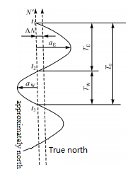
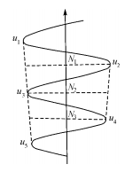
The reversal point method uses a gyro-theodolite to track and observe the horizontal dial readings when the swinging index line (gyro axis) repeatedly reaches the east and west reversal points, and determines the true north direction of the station through calculation. This method requires keeping the instrument stable during the observation process to ensure accurate readings.

Figure 1 Observation using the reversal point method


The Zhongtian Rule is to first determine the approximate north direction by observing the operation of the gyroscope axis, and then continuously read and record the time when the swinging indicator line (gyro axis) repeatedly passes through the zero line of the reticle plate, and reaches the east and west reversal points. The horizontal dial reading at the time. Through calculation, the correction number of the approximate north direction can be obtained, and then the true north direction of the station can be determined. This method requires precise control of observation times and readings to obtain accurate orientation results.

Figure 2 Observation using the reversal point method


Summarize

To sum up, the gyro theodolite achieves high-precision measurement of geographical coordinates by utilizing the gyro's fixed axis and precession properties. In theoretical research and practice, the following consensus has been gradually reached on the number of additional gyroscopic edges: adding gyroscopic edges in long underground wires can effectively control and reduce lateral errors and improve accuracy. Compared with the azimuth angle without additional measurement of the gyro side, the accuracy gain is larger. When one additional side is measured, the gain is 50% to 60%; when three additional sides are measured, the gain is 75% to 80%. If there are more than 3 gyro edges, the gain is not obvious. From the perspective of improving accuracy and measuring personnel's workload, it is appropriate to measure 1 to 2 more gyro edges.

As the accuracy of gyroscopes gradually improves, the advantages of gyroscope orientation will become more obvious, and their application in underground engineering conductors such as mines and tunnels will become more common. ERICCO's gyro theodolite, such as ER-GT-02 and ER-GT-03:


ER-GT-02 (≤3.6") Features:

  1. Orienteering accuracy ≤3.6" (1σ);
  2. Pit interference ability is strong, integrated fuselage design, compact structure, stable performance;
  3. Has the functions of low lock, automatic zero observation and etc.


ER-GT-03 (≤30")Features:

  1. Orienteering accuracy ≤30" (1σ);
  2. Volume (no theodolite) ≤Φ200mm×h490mm.


Welcome to learn more, please contact us.

Monday, April 8, 2024

The Ultimate Precision Sensor Fiber Optic Gyroscope


1.Use light to calculate movement

Based on the Sagnac effect, fiber optic gyroscopes are passive systems that use light to calculate motion. Rotational motion is measured by sending the same laser beam in opposite directions through a long fiber optic coil. A laser beam in the opposite direction of rotation experiences a slightly shorter path delay than other beams. Measuring the phase shift between the two beams reveals the change in direction. Ericco's fiber-optic inertial navigation system consists of three FOG gyroscopes that measure rotation on three different axes of freely rotating objects in three dimensions. Ericco fully grasps the technology through vertical integration, has end-to-end control over the quality of the fiber optic gyro, and the control and adaptability of the product performance is the guarantee of quality and excellence.
Ericco has extensive experience in all markets, making full use of its inertial navigation experience in various markets. As a result, you have gained extensive knowledge and experience of FOG technology used in the field. As a result, our company is able to continuously develop and adapt its advanced algorithms to meet the changing requirements of our customers' daily operations.

2. Fiber optic gyro performance

We offer unmatched performance, scalable technology for all types of applications. The performance of the fiber optic gyroscope can be changed by changing the length and diameter of its coil, (we all know that the accuracy of the fiber optic gyroscope is determined by the length of the fiber, the longer the fiber length, the diameter is naturally large, the higher the accuracy, on the contrary, the accuracy is low). This enables it to adapt to a wide range of performance requirements. By pushing the technical limits of the optical components used in the FOG gyro, performance can also be further improved.

Because Ericco has complete control of all the components integrated into its systems, from its own fibers and components, to accelerometers and algorithms, the company can push the limits of FOG technology and take it to new performance peaks.
Fiber optic gyroscopes offer unparalleled reliability and are truly solid state passive systems. In fact, fiber optic gyro technology does not involve any movement of mechanical parts, will not cause jitter, vibration, friction, resulting in component wear and noise. This ensures many benefits for the user: acoustic stealth, system robustness (forget when you turn it on), cost effectiveness and the lowest cost on the market.
Fiber-optic gyroscopes offer unrivalled reliability, operating as a single component and relying solely on light motion, resistant to external interference such as shock, extreme temperature, magnetism or vibration. That's why fiber optic gyroscopes are equipped with systems that operate in extreme environments or expect sensors with high resistance: satellites, strategic submarines, long-range artillery, extreme deep water robots, and vehicles.

3. Summary

Ericco has a single axis, two axis, three axis profiled fiber optic gyro. Medium precision is very popular, and the application field is also very wide, such as optical pods, flight control platforms, inertial navigation systems, inertial measurement units, platform stabilizers, positioning systems, north finder, high precision measurement, navigation systems and servo systems. For example, ER-FOG-50 (0.2~2.0º/h), ER-FOG-60 (0.06~0.5º/h), ER-FOG-70 (0.05~0.8º/h), the parentheses are the zero-bias stability of fiber optic gyroscope. As we all know, zero-bias stability is one of the important indicators to evaluate the performance of a gyroscope. These are our hot selling products, they have a small size, light weight, pure solid, because there is no friction and moving parts, so long service life, if you are interested in any of our fiber optic gyro, want to get more technical data, please feel free to contact us.

Sunday, April 7, 2024

What is a Fiber Optic Rate Gyroscope?


1. Basic knowledge of gyroscope

A gyroscope is a device that can sense direction and angular speed. The simplest type of gyroscope is based on a rotating wheel that is fixed to the frame - many people think of it as a children's toy. Even if the frame around the wheel rotates, angular momentum keeps the direction of the wheel the same.
With the development of flying machines (airplanes and rockets) in the 20th century, gyroscopes were no longer just toys. The reason for this is that flying vehicles have navigational requirements that ground vehicles or even ships do not. That is, they can rotate and move freely in all three dimensions. Therefore, the pilot needs to constantly know the direction of the vehicle on the three axes to control the aircraft.
Unmanned rockets and missiles have further requirements. These aircraft need to know their direction and position without the need for human pilots to monitor them. The solution is the Inertial Guidance System (IGS). IGS uses gyroscopes to sense direction and angular motion to continuously control the vehicle and calculate its distance from the starting point.

2. What is a fiber optic rate gyroscope?

Fiber optic rate gyroscope (FOG) is a high precision rotating sensor. They are used in navigation and guidance systems for aircraft, spacecraft, ships and other vehicles. They sense rotation by measuring the interference of laser light propagating within the fiber coil.


3. Advantages of fiber optic gyroscope

The first gyroscopes were mechanical - a motor-driven rotating rotor and various sensors to read angular speed and direction information and provide it to a human pilot or IGS. These mechanical gyroscopes are relatively large and heavy. Their performance can be affected by vibration and require frequent calibration.
The interferometric fiber optic rate gyroscope was developed to overcome the limitations of mechanical gyroscopes. They use fiber coils, coherent light sources, and photodetectors to sense rotation instead of mechanical rotors. This results in smaller, lighter and more accurate systems.
Inside the FOG, the light source is split into two beams before entering the fiber coil. Two beams of light are coupled to opposite ends of the fiber so that one beam travels in a clockwise direction and the other in a counterclockwise direction.
If the coil rotates about its axis, the two beams will undergo a phase shift relative to each other. This is called the Sagnac effect. When the two beams leave the fiber, they recombine. Any phase shift creates interference fringes in the combined beam. The detector senses this pattern to determine the angular speed of rotation. Typically, three coils (each mounted at right angles to the other two) are used to sense rotation on all three axes simultaneously.
But all of these different design forms have fairly similar requirements for the fiber optic coil at the center of the system. In particular, certain parameters are critical to the normal performance of the FOG. The most important are insertion loss, polarization extinction ratio (PER) and wavelength-dependent loss. Winding accuracy and packaging quality are also important.
To achieve good performance in these areas requires the ability to tightly control the manufacture of the fiber itself, as well as the process of winding it into a coil. In particular, the fiber coil must be wound in a perfectly symmetrical manner (so that a beam traveling in the opposite direction experiences the same conditions). In addition, it is also important to minimize the mechanical stress in the wound fiber.

4. FOG at work

FOG offers several significant advantages over conventional gyroscopes and even other non-mechanical technologies. For one thing, FOG is very sensitive and can detect very small rotational motions - angular velocities with a resolution of a few nanoradians per second. That's orders of magnitude better than a mechanical gyroscope. As a result, they provide more precise navigation and guidance.
In addition, FOG is relatively free from vibration and electromagnetic interference, and has a long service life and low maintenance requirements. This makes them useful in a variety of "harsh" environments or places where device access is limited. This includes spaceborne applications as well as inertial measurement systems for offshore and underwater vehicles and equipment.
Due to its high sensitivity and accuracy, FOG is also commonly used to stabilize fixed structures. For example, FOG can measure the rotating motion of structures such as Bridges, buildings, or antenna platforms and feed the data back to a control system that compensates for any movement. This helps to maintain the stability of the structure, especially in strong winds or earthquake conditions.

5. Summary

In short, the FOG is a high-precision and accurate rotation sensor with a wide range of applications. They are free from electromagnetic interference, relatively immune to vibration, have a long service life, low maintenance requirements, and are relatively small and lightweight. This makes them ideal for use in navigation, guidance and control systems for aircraft, ships and ground vehicles. In addition, they are useful in industrial automation and robotics.
Ericco's ER-FOG-851ER-FOG-910 are two very popular fiber optic rate gyroscopes, with fast start, simple operation, easy to use and other characteristics, widely used in INS, IMU, positioning system, north finding system, platform stability and other fields. If you would like more technical data, please feel free to contact us.

Saturday, April 6, 2024

Take you to briefly understand IMU

 https://www.ericcointernational.com/application/take-you-to-briefly-understand-imu.html

IMU is the abbreviation of Inertial Measurement Unit. It is a sensor composed of an accelerometer, a gyroscope and a magnetometer, which is used to measure the motion status of an object such as angle, speed and acceleration. The accelerometer is used to measure the object's acceleration and gravity, the gyroscope is used to measure the object's angular velocity and gravity, the gyroscope is used to measure the object's angular velocity, and the magnetometer is used to compensate for the interference of the geomagnetic field on the gyroscope.


As the core component of the inertial navigation system, IMU can help the system achieve autonomous navigation and positioning without being restricted by GPS, and has wide application value. It can play a role in a variety of fields such as drones, robots, missiles, aircraft, ships, camera stabilizers, etc. The magnetometer is used to compensate for the interference of the geomagnetic field on the gyroscope. The technology and parameters of IMU will be introduced below.

Features of IMU technology:

  1. High accuracy: IMU can achieve high-precision measurement and prediction of motion status, and can achieve high measurement accuracy.
  2. Compact and lightweight: The IMU is very small and can be equipped on various devices, such as drones, robots, etc.
  3. Degree of freedom of motion: IMU can measure acceleration, angular velocity and magnetic field in three axes, and can achieve various combinations of six axes, nine axes, etc. to meet the needs of different applications.
  4. Low energy consumption: The IMU has very low power consumption and can meet the needs of long-term continuous use.

Parameters of IMU technology:

  1. Accelerometer: It can measure the acceleration of an object (including static and dynamic acceleration) and the acceleration of gravity, and can also measure the inclination angle of the object.
  2. Gyroscope:It can measure the angular velocity of an object, also known as the rotational speed or rotation rate of the object.
  3. Magnetometer: It can measure the geomagnetic field and can be used to help solve the direction and angle of objects.
  4. Data frequency:IMU can output data at different frequencies, such as 100Hz, 200Hz or 1000Hz. The higher the data frequency, the stronger the real-time nature of the data.

Application areas

IMU technology is widely used, from satellites to subways, from aircraft to spacecraft, from drones to robots, everywhere. It can help devices achieve autonomous navigation and positioning, and can also be used in areas such as attitude sensing, tilt compensation, and vibration suppression. IMU technology is widely used in military, civilian, scientific and medical fields.


The emergence of IMU technology makes up for the shortcomings of GPS positioning. The two complement each other and enable autonomous vehicles to obtain the most accurate positioning information. It is worth noting that the IMU provides relative positioning information. Its function is to measure the path of an object relative to a starting point, so it cannot provide specific location information about your location. So often used with GPS. When in some places where the GPS signal is weak, the IMU can play its role, allowing the car to continuously obtain absolute position information to avoid getting "lost." In fact, although the IMU technology seems strange, in fact, IMU is used in the mobile phones, cars, airplanes, and even missiles and spacecraft that we use daily. The difference is cost and accuracy.


According to different usage scenarios, there are different requirements for the accuracy of IMU. High precision also means high cost.


Low-precision IMU: Used in general consumer electronics, this low-precision IMU is very cheap. Widely used in mobile phones and sports watches, often used to record steps. ​


Medium-precision IMU: used in driverless cars, with prices ranging from a few hundred to tens of thousands of dollars, depending on the positioning accuracy requirements of the driverless car.


High-precision IMU: for missiles or space shuttles. Take missiles for example. From the time the missile is launched to hitting the target, the aerospace IMU can achieve very high-precision calculations, and the error can even be within one meter.

Conclusion

IMU technology has been developing rapidly. With technological innovation in various fields, the application scenarios of IMU technology will become more and more extensive.ERICCO INERTIAL SYSTEM has conducted more in-depth research on IMUs. For example, ER-MIMU01 can independently seek north and uses high-quality and reliable MEMS accelerometers and gyroscopes. It is equipped with X, Y, Z three-axis precision gyroscopes, X, Y, Z three-axis accelerometer, with high resolution, can output the original hexadecimal complement data of X, Y, Z three-axis gyroscope and accelerometer through RS422 (including gyroscope hexadecimal complement) numerical temperature, angle , accelerometer hexadecimal temperature, acceleration hexadecimal complement); it can also output floating point dimensionless values of gyroscopes and accelerometers processed by underlying calculations. If you want to better study and master IMU technology, it is necessary to study subjects such as physics, mathematics, and computer science. I hope this article will help you understand IMU. Ericco also has a variety of high-precision IMUs. Welcome to learn more!


Tuesday, April 2, 2024

Miniaturized FOG Inertial Measurement Unit

 Fiber optic gyroscope is a new type of angular velocity sensor based on Sagnac effect. Compared with mechanical gyroscope, fiber optic gyroscope has the advantages of all-solid structure, strong impact resistance and short start-up time. Compared with laser gyro, it uses passive fiber ring as the sensitive medium and has no blocking effect.

Since Vali and Shorthill demonstrated the feasibility of measuring angular velocity in the laboratory with the Sagnac interferometer in 1976, more than four decades of technological progress have been made. At home and abroad, including Honeywell, NorthropGrumman, Liton, Beijing University of Aeronautics and Astronautics, the 33rd Aerospace Science and Industry Group, the 502nd Aerospace Science and Technology Group, Ericco and other units have developed mature fiber optic gyro products, measuring accuracy covers high, medium and low precision applications. And has begun mass production, in many fields have replaced the traditional mechanical gyroscope.


Inertial measurement unit (IMU) is the core component of inertial navigation system (INS). With the development of fiber optic gyroscope technology, the FOG Inertial Measurement Unit as the angular velocity sensitive component has been maturely applied in aviation, aerospace, weapons and other fields, greatly improving the performance of inertial navigation system. However, in some special fields such as deep space exploration and manned spaceflight, the inertial navigation system has higher requirements for the volume, power consumption and reliability of FOG Inertial Measurement Unit due to the constraints of space environment and spacecraft loads. In order to meet the application requirements of miniaturized and low-power FOG Inertial Measurement Unit for inertial navigation systems in aerospace market, a design and implementation method of miniaturized FOG Inertial Measurement Unit is proposed. The results show that the weight of IMU components is 2.342 Kg, and the power consumption is 10.6 W at normal temperature, which can meet the requirements of IMU in inertial navigation system.


1. IMU design scheme
The framework of the miniaturized FOG Inertial Measurement Unit is proposed, which consists of two parts: IMU module and IMU circuit. The IMU assembly consists of four fiber optic gyroscopes and four quartz flexible accelerometers. The fiber optic gyroscopes/accelerometers receive the secondary power supply provided by the IMU line and output telemetry and pulse signals. The IMU component adopts the 4S structure scheme, and any three-axis fiber optic gyro/accelerometer can complete the angular velocity/acceleration measurement function, with 1 degree redundancy. The IMU circuit consists of a primary interface circuit, a backup interface circuit, and a power management circuit. The primary and backup interface circuits have the same functions and are used in cold backup. The interface circuit receives the primary power supply provided by the inertial navigation system, provides the secondary power supply to the fiber optic gyro/accelerometer, collects the output signal of the fiber optic gyro/accelerometer, and communicates with the inertial navigation system. The power management circuit works with the main and backup interface circuits to complete the independent power-on and power-off control of four fiber optic gyros and four accelerometers.
Interface circuit, power management circuit, accelerometer, fiber optic gyro are the important components of IMU, and their volume and power consumption directly affect the product status of IMU. After more than 40 years of technological progress, the technology of miniaturized fiber optic gyroscope has been relatively mature.


2. Design results
Through the interface circuit based on SIP device LSMEU01 and the miniaturized power management circuit based on magnetic hold relay, the volume of IMU circuit is reduced by about 1/2 and the weight is reduced to 0.778 Kg. The single-meter power consumption of the accelerometer is reduced to 0.9W by using the temperature compensation method based on the combined parameters. By using this measure, we can effectively reduce the volume and power consumption of IMU. The results show that the weight of IMU components is 2.342 Kg and the power consumption is 10.6W at normal temperature, which can meet the needs of the use of minisized IMU in inertial navigation system.


3. Summary
Ericco's ER-FIMU-50 is the smallest FOG Inertial Measurement Unit, which is widely used in AHRS, guidance and control systems, onboard attitude measurement inertial/satellite integrated navigation system, drilling system mobile mapping system, and satellite communication in motion. If you would like to obtain more technical data, please feel free to contact us.

Thursday, March 28, 2024

Large Outdoor Advertising Monitoring Based on Tilt Sensor

 When it comes to the use of tilt sensors to monitor angles, people's first reaction may feel very strange, in fact, we often use the mobile phone has a similar function, it is easy to search the relevant app in the mobile app store, and it is also very convenient to use, although there may be no one in the work really use the mobile phone as a measurement tool. But we can fully see that the measurement of the tilt Angle has been very easy.

At present, the inclination sensors used in many fields are basically based on MEMS (Micro-electro Mechanical System for short, Chinese name micro-electro-mechanical system) tilt sensors, around 1960, the United States took the lead in studying MEMS technology, Then France, Germany, Switzerland, Japan and other countries also began to pay attention to MEMS research work, China's MEMS research began in 1989, to 1999, China's domestic MEMS research and development units have reached more than 50, the level of scientific research can also be placed in the international top ten. As of 2010, there are about 600 units engaged in the research and production of MEMS in the world.
MEMS is an independent intelligent system, which integrates micro sensor, signal processing, actuator, interface circuit, control circuit, communication and power supply in one. It has the advantages of small size, low power consumption, light weight, strong durability, high stability, low price and easy mass production. It can be seen that MEMS refers to a system that is integrated by multiple devices. The current research on MEMS technology mainly includes: micro-mechanical pressure sensor, micro-gas sensor, micro-acceleration sensor, micro-flow sensor, micro-mechanical gyroscope, micro-mechanical temperature sensor and other micro-mechanical sensors.
Mems-based sensors have many uses, measuring tilt angle is just one of them, using acceleration sensors, such as gas flow measurement, temperature measurement, pressure measurement, and so on.
The application of MEMS technology to monitor the tilt angle of large outdoor advertisements is not a blind decision.

1. Monitoring methods for large-scale outdoor advertising
At present, there are four main monitoring methods for large-scale outdoor advertising:

(1) Camera monitoring
Due to the large outdoor advertising area is large, very eye-catching, mostly erected in bustling areas, highways and overpasses near, these geographical locations are also key jurisdiction areas of the city, therefore, these areas are basically covered by urban surveillance cameras, administrators can view large advertising and its surrounding situation through real-time monitoring. Although this monitoring method seems to have the characteristics of real-time, but it is difficult to achieve in practical applications, the monitor can not always stare at the surveillance video, and when the visibility is low, the effect of the surveillance video will be reduced a lot, affecting the observation of the monitor, therefore, the use of this method to monitor large-scale advertising is not ideal.

(2) Regular manual inspection
Surveyors field measurement is the most traditional monitoring method, the longest application time, the monitoring process is relatively mature,
This method is mainly used by inspectors to measure large advertisements using steel tape, optical theodolite, portable ultrasonic flaw detector, weld gauge, rebound meter and other equipment. Due to the support of high-precision data, this method has high credibility, but in order to achieve rapid and comprehensive monitoring of all large advertisements, not only need multiple sets of monitoring equipment. It also needs to use more manpower and material resources, which is very inconvenient, and this method is mainly preventive, which cannot achieve real-time understanding of large-scale advertising conditions, so this method is not ideal.

(3) Monitoring based on radio frequency technology
The technology is a non-contact automatic identification technology that emerged around 1990, which carries out non-contact two-way data transmission between the base station and the radio frequency card to achieve the purpose of identifying the target and data transmission. This method mainly uses 2.4GHz active radio frequency electronic tag to record the attribute information and location information of large advertisements. The electronic tag can sense the displacement, and a receiving base station is required to receive, process and transmit the data sent by the electronic tag. The technology is widely used in many fields such as small advertising management, highway ETC express lanes, logistics, retail and so on.
Although this method can obtain the position data of large advertisements in real time, it is not its strong point in monitoring the tilt Angle. This method can make up for the shortcomings of the above two methods, but the final result can not measure the tilt of large advertisements

(4) Sensor-based inclination monitoring
Tilt sensor is often used to measure the change in inclination relative to the horizontal plane, it is based on Newton's second law as a theory, according to the basic principles of physics, in a system, the speed can not be measured, but can measure its acceleration, under the condition of the initial speed is known, you can use the integral method to calculate the line speed, and then calculate the linear displacement. So it's an acceleration sensor that uses the principle of inertia. The tilt sensor is fixed on the back of a large advertisement, and the single chip microcomputer is used as the central controller to integrate the monitored angle data, monitoring time, monitoring site number and other information, and then through the General Packet Radio Service (GPRS), The wireless communication module will send out the packaged data, and the data will be analyzed and processed by the monitoring personnel, and this equipment is powered by solar energy + battery, making the equipment more independent and easier to manage. This method can understand the angle information of large advertisements in real time. In the case of investing very little manpower and material resources, you can fully understand the situation of each large advertisement, and the data credibility is high, so this way is more ideal.

2 Summary
In summary, after a more detailed analysis of various monitoring methods, it is not difficult to see that the method based on tilt sensors is the best to use this method to monitor the tilt of large-scale outdoor advertising. Ericco has various precision and types of tilt sensors, like ER-TS-3160VOER-TS-12200-Modbus, widely used in Bridges, DAMS, building monitoring and other fields, if you want to buy or want more technical data of tilt sensor, you can contact us at any time.

Choose a suitable IMU to make your drone flight more stable and safe

         As one of the core components of drones, IMU plays an irreplaceable role. Its high precision, fast response and freedom from extern...